
Additional steps to those outlined:
emerge alsa-firmware
and... modprobe snd_hdsp
Changes also to cur to compile for GCC 4.1.1:
http://1010.co.uk/cur2-rme-feb2007.tar.gz
1] Added library for the older but more manageable FT232BL USB UART (USB to serial) component using online library component builder at:
http://www.rohrbacher.net/kicad/quicklib.php
library is at:
http://1010.co.uk/images/FT232BL.lib
packaging is TQFP32
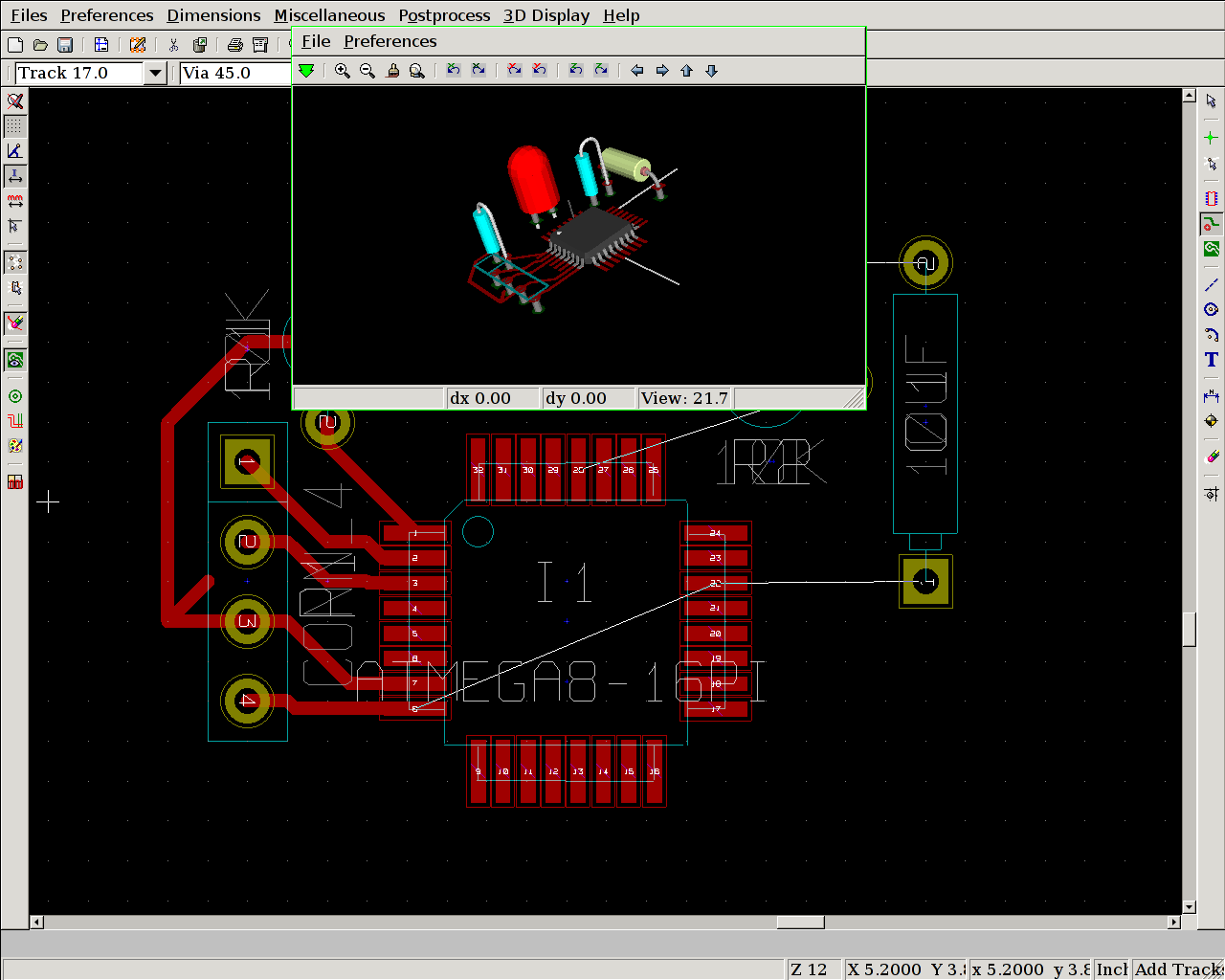
2] Schematic is at:
http://1010.co.uk/images/atmega8usb.pdf
(note older PCB screenshot is incorrect)
3] 3 projected boards - independent UART and ATmega8 with circles for cpu_model, and both combined as above for 8 bit data interface sans parallel port
rough idea to edit video in Emacs Lisp:
http://www.gnu.org/software/emms/
;; emms-player-mplayer.el --- mplayer support for EMMS

(defun emms-player-mplayer-seek (sec)
  "Depends on mplayer's -slave mode."
  (process-send-string
   emms-player-simple-process-name
   (format "pausing seek %d\n" sec)))
with subtitles and obviously using free software on GNU/Linux...
1] Using mencoder with subtitles specified a la:
/usr/bin/mencoder -of mpeg -mpegopts format=dvd -srate 48000 -ofps 25 -ovc lavc -oac lavc -lavcopts vcodec=mpeg2video:vrc_buf_size=1835:keyint=15:vrc_maxrate=9800:vbitrate=9800:acodec=ac3:aspect=4/3:abitrate=192 thefilm.avi -o test.mpeg2 -sub thesubtitles.srt -font ~/.mplayer/subfont.ttf -subfont-text-scale 3
breaks aspect with dvdauthor: unknown mpeg2 aspect ratio 1
results in DVD image with an incorrect aspect
note also the subfont.ttf as in previous attempts we couldn't scale the font
font can also be specified in ~/.mplayer/mencoder.conf:
font=~/.mplayer/subfont.ttf
Encoding to mpeg2 using ffmpeg works fine with dvdauthor and aspect but using spumux to add subtitles doesn't work - spumux 0.6.13 and darcs version result in drastic memory leaks.
2] Clumsy fix uses two passes:
mencoder thefilm.avi -ovc lavc -oac lavc -lavcopts aspect=4/3 -sub thesubtitles.srt -subfont-text-scale 3 -o outputfilm.avi

## then:

ffmpeg -i outputfilm.avi -target pal-dvd -aspect 4:3 test.mpeg2

## and then the usual processing with dvdauthor

/usr/bin/dvdauthor -o ~/dvd -x ~/structure.xml

mkisofs -dvd-video -o test.iso ~/dvd/

##finally

growisofs -dvd-compat -Z /dev/dvd=test.iso
for extra good measure dvdauthor's structure.xml:
<dvdauthor>
  <vmgm>
<menus>
<video format="pal" aspect="4:3" />
</menus>
</vmgm>
  <titleset>
    <titles>
      <pgc>
        <vob file="~/test.mpeg2"/>
      </pgc>
    </titles>
  </titleset>
</dvdauthor>

Computer controlled permutative switching of circuits (allows for 16 points to be connected) using 3 bits (serial data transmission) over USB or parallel port. Modular design of 2 serial/parallel boards (74HC595 shift register chips see: http://computerchristmas.com/index.phtml?link=how_to&:=25) and 4 switch boards (4016/4066 quad bilateral switches): http://www.doctronics.co.uk/4016.htm. Switching points are also exposed to CV (control voltage).
http://users.tkk.fi/~jwagner/electr/dc-rx/PCB_devel.htm
1] Straight print from PCBNEW menu under a range of options is unusable (tracks joined, offset and pads connected randomly).
2] Choose plot with Postscript option from file menu and write (in this case) xxxxx-Component.ps. Printing from this using gv is better but unusable also.
3] Run ps2pdf on this .ps and open resulting .pdf with xpdf. Print from this.
(further notes: print command for our CUPS shared printer is lpr -P printer, resolution was set by way of web interface to 600 dpi)
next stage exposure (UV light) and photoresist:
http://www.electricstuff.co.uk/pcbs.html
dev-lang/python-2.4.3-r1 does not actually support the tk USE flag!
when emerging the gimp:
fix at:
http://www.linuxforums.org/forum/gentoo-linux-help/75725-installing-gnome.html
USE="-tk" emerge -av python
and then emerge gimp (again)
Following: http://thomasgersdorf.com/linux/index.php/Gentoo_Linux_on_IBM_ThinkPad_T60:Fn-Keys
For power management/suspend to RAM and function keys use. No mention of AHCI in Thinkpad BIOS. Enabled sleep states under ACPI in stock 2.6.18 kernel. Emerged: acpid, and thinkpad - previously tpctl stuff also.
xxxxx: rc-update add acpid default
reboot and now: echo -n mem > /sys/power/state
suspends with use of crescent-moon function-F4 to wake up!
Loosely following excellent tutorial at:
http://www.kicadlib.org/Fichiers/:_Tutorial.pdf
as referenced from:
[question remains of how to adapt drawing for mandalas offering up GND, 5V, TX, RD serial circling the central processor - perhaps making use of graphic drawing (only of use on silkscreen layers) and print these at same time]
http://kicad.bokeoa.com/wiki/index.php/Mini_tutorial
http://www.neilvandyke.org/quack/
1] download and (require 'quack) in .emacs
http://www.neilvandyke.org/quack/quack.el
2] default fontlock for ;;; comments (three semicolons) is blue text-invisible bars. change this with:
(setq quack-fontify-threesemi-p nil)
3] Key bindings:
;;     The key bindings that Quack adds to `scheme-mode' include:
;;
;;         C-c C-q m   View a manual in your Web browser.
;;         C-c C-q k   View the manual documentation for a keyword
;;                     (currently only works for PLT manuals).
;;         C-c C-q s   View an SRFI. (Scheme Requests for Implementation)
;;         C-c C-q r   Run an inferior Scheme process.
;;         C-c C-q f   Find a file using context of point for default.
;;         C-c C-q l   Toggle `lambda' syntax of `define'-like form.
;;         C-c C-q t   Tidy the formatting of the buffer.
Followed instructions at: http://bc.tech.coop/blog/060529.html
(using c key here within Conkeror to copy current link)
and:
http://conkeror.mozdev.org/installation.html
Numbered links: we simply enter the number
To find out more: C-h-i Man page (C- is control M- is meta) or C-h-b - list of all bindings
Simple stuff:
g - open new location
B and F - backwards and forwards
C-x-r-b - jump to bookmark
C-x-r-l - show all bookmarks
ESC to exit text box entry
and usual Emacs bindings - C-s for search which (in caret mode after hitting F7) also highlights and can thus be M-w into killring
One question: how do we access history... history.js?
1] Using old MAX3232 circuit from PIC times (see http://www.geocities.com/vsurducan/electro/PIC/pic84lcd.htm) with pin 11 of 3232 (T1IN) to TX pin 3 on ATmega, 12 (R1OUT) to RX pin 2.
2] 1 MHz is factory default internal oscillator frequency which we CAN change with Guido's prg_fusebit_uc script (1 MHz means we have to stay at 2400 baud and this is as set in minicom: 2400 8N1) - can only be changed without external oscillator upto 8 MHz
3] Sample serial writing code as follows:
#include <stdio.h>
#include <avr/io.h>
#include <inttypes.h>
#define F_CPU 1000000UL  // 1 MHz
#include <avr/delay.h>

#define BAUD 2400

#define F_OSC 1000000 //default setting
#define UART_BAUD_RATE 2400
#define UART_BAUD_CALC(UART_BAUD_RATE,F_OSC) ((F_OSC)/((UART_BAUD_RATE)*16l)-1)

void init_uart(void)
{
  // set baud rate
  UBRRH = (uint8_t)(UART_BAUD_CALC(UART_BAUD_RATE,F_OSC)>>8);
  UBRRL = (uint8_t)UART_BAUD_CALC(UART_BAUD_RATE,F_OSC);

  // Enable receiver and transmitter; enable RX interrupt
  UCSRB = (1<<RXEN) | (1<<TXEN);

  //asynchronous 8N1
  UCSRC = (1<<URSEL) | (3<<UCSZ0);
}

static int uart_putchar(char c, FILE *stream);

static FILE mystdout = FDEV_SETUP_STREAM(uart_putchar, NULL,_FDEV_SETUP_WRITE);

static int uart_putchar(char c, FILE *stream)
{

  if (c == '\n')
    uart_putchar('\r', stream);
  loop_until_bit_is_set(UCSRA, UDRE);
  UDR = c;
  return 0;
}

int
main(void)
{
   init_uart();
  stdout = &mystdout;

  while(1) printf("help!");
  return 0;
}
4] serial echo (read/write echoes characters typed from miniterm based on wiring.c from Arduino):
http://1010.co.uk/testserial.c
5] Forgot that Emacs/Brood code of Tom Schouten's is all wrapped up in Forth... should be easy enough to use PLT or other Lisp/Scheme to wrap up communications with the scrying scheme board.
6] Next step is to use the LQFP32 packaged FT232BL (not R) board -
Kicad program for schematics looks good but we will have to modify the 232R component (both SMD and DIL ATmegas are available in additional libraries).
links:
Kicad: http://www.lis.inpg.fr/realise_au_lis/kicad/
Libraries: http://www.kicadlib.org/
(Oregano (limited as to component libraries), and Xcircuit also as possible schematic capture offerings).
to edit a schematic and generate a netlist before we make a PCB design in pcb (all GNU free software) - pcb is installed under Gentoo with seperate emerge command.
gschem (also gattrib for editing attributes of .sch files)
http://geda.seul.org/wiki/geda:gschem_ug
and the warmup:
http://www.geda.seul.org/docs/current/tutorials/gsch2pcb/gschem-warmup.html
perhaps try CVS version
Progress so far:
What are the differences here between Default - reference component, embed component and component as individual objects (latter option seperates out and can thus be edited)?
Use reference I think...
ATmega8 component lacks VCC and GND and pin 1 is in an awkward place. First two remedied by modal operation/keystroke driven approach ... where we want pin ap keys and pull line with left mouse into body of chip. middle mouse to stop behaviour. an to add net/wire with similar results. select object with left mouse squaring over and add aa to attach/add attribute such as a pin number. ea to edit attributes of selected piece/element.
er to rotate elements, fs to save, z and Z to zoom, w to zoom next selected square, ve to view extents (?)
But how do we edit the ATmega8 stuff as it stands to switch pin 1?
(only problem is crashes on update)
see Wiki above:
Update Component (ep)
(we can use gattrib to edit attributes which are things like names/values/pin assignments but ...)
warmup above is a good place to start for simple operations.
note also:
it only makes sense to create pins while creating or editing symbol files...
note also url for gattrib: http://www.brorson.com/gEDA/gattrib/
ATmega8 platform, using free software tools, and based on Steele and Sussman's Design of Lisp-based Processors, and Abelson and Sussman's
;;;;EXPLICIT-CONTROL EVALUATOR FROM SECTION 5.4 OF ;;;; STRUCTURE AND INTERPRETATION OF COMPUTER PROGRAMS
;;SECTION 5.4.1
eval-dispatch
  (test (op self-evaluating?) (reg exp))
  (branch (label ev-self-eval))
  (test (op variable?) (reg exp))
  (branch (label ev-variable))
  (test (op quoted?) (reg exp))
  (branch (label ev-quoted))
  (test (op assignment?) (reg exp))
  (branch (label ev-assignment))
  (test (op definition?) (reg exp))
  (branch (label ev-definition))
  (test (op if?) (reg exp))
  (branch (label ev-if))
  (test (op lambda?) (reg exp))
  (branch (label ev-lambda))
  (test (op begin?) (reg exp))
  (branch (label ev-begin))
  (test (op application?) (reg exp))
  (branch (label ev-application))
  (goto (label unknown-expression-type))
also a pinch of Chaitin's C Lisp interpreter...
http://tuxgraphics.org/common/src2/article352/Makefile.html
in contrast Steele and Sussman make use of a 3 bit type field (plus 8 bits for the address) for 7 types (thus 256x 11 bit words)
#define CONSTANTL 0
#define CONSTANTS 1
#define VAREF 2
#define CC 3
#define PROC 4
#define COND 5
#define PROCEDURE 6
#define QUOTE 7
further storage notes (Steel/Sussman):
The method we use for implementing CAR, CDR and CONS is the usual one of using two consecutive words of memory to hold a list cell, the first being the cdr and the second the car, where each word of memory can hold a type field and an address field. The address part of the pointer is in turn the address within the linear memory of the record pointed to.
Abelson and Sussman use two vectors: the_cars and the_cdrs
http://mitpress.mit.edu/sicp/full-text/book/book-Z-H-33.html
We can use vectors to implement the basic pair structures required for a list-structured memory. Let us imagine that computer memory is divided into two vectors: the-cars and the-cdrs. We will represent list structure as follows: A pointer to a pair is an index into the two vectors. The car of the pair is the entry in the-cars with the designated index, and the cdr of the pair is the entry in the-cdrs with the designated index. We also need a representation for objects other than pairs (such as numbers and symbols) and a way to distinguish one kind of data from another. There are many methods of accomplishing this, but they all reduce to using typed pointers, that is, to extending the notion of “pointer” to include information on data type.7 The data type enables the system to distinguish a pointer to a pair (which consists of the “pair” data type and an index into the memory vectors) from pointers to other kinds of data (which consist of some other data type and whatever is being used to represent data of that type). Two data objects are considered to be the same (eq?) if their pointers are identical.
further:
The reader maintains a table, traditionally called the obarray, of all the symbols it has ever encountered. When the reader encounters a character string and is about to construct a symbol, it checks the obarray to see if it has ever before seen the same character string. If it has not, it uses the characters to construct a new symbol (a typed pointer to a new character sequence) and enters this pointer in the obarray. If the reader has seen the string before, it returns the symbol pointer stored in the obarray. This process of replacing character strings by unique pointers is called interning symbols.
cons as:
(perform
 (op vector-set!) (reg the-cars) (reg free) (reg <reg2>))
(perform
 (op vector-set!) (reg the-cdrs) (reg free) (reg <reg3>))
(assign <reg1> (reg free))
(assign free (op +) (reg free) (const 1))
further instruction summary:
A controller instruction in our register-machine language has one of
the following forms, where each <inputi> is either (reg
<register-name>) or (const <constant-value>).

These instructions were introduced in section 5.1.1:

(assign <register-name> (reg <register-name>))

(assign <register-name> (const <constant-value>))

(assign <register-name> (op <operation-name>) <input1> ... <inputn>)

(perform (op <operation-name>) <input1> ... <inputn>)

(test (op <operation-name>) <input1> ... <inputn>)

(branch (label <label-name>))

(goto (label <label-name>))

The use of registers to hold labels was introduced in section 5.1.3:

(assign <register-name> (label <label-name>))

(goto (reg <register-name>))

Instructions to use the stack were introduced in section 5.1.4:

(save <register-name>)
http://repository.readscheme.org/ftp/papers/ai-lab-pubs/AIM-453.pdf
further Scheme research:
icbins: from http://www.accesscom.com/~darius/
with further interesting code there...
from the README from icbins:
Here we have an exercise in stripping a Lisp to barest essentials, dropping the host tether early, and repeatedly changing and rebuilding, to practice evolving a self-hosted system. Only the garbage collector and the lowest-level Lisp primitives are in C. The source is an order of magnitude smaller than the already-lightweight UTS's. You might find this of interest if you want to do similar exercises or if you'd just like to read a tiny Lisp system with no magic (small self-hosting Lisps typically rely on powerful primitives like READ, PRINT, and GC). This could be cut down further; hopefully I'll come back to it someday.
-a) checl we have ftdi_sio and usbserial modules built and loaded
a) we have the Arduino codebase
b) on Gentoo: emerge crossdev (had to first set PORTDIR_OVERLAY=/usr/portage in /etc/make.conf)
takes some time...
c) emerge avrdude programming utility AFTER b) succeeds
d) check out Makefile and modify as below
# Arduino makefile
#
# This makefile allows you to build sketches from the command line
# without the Arduino environment (or Java).
#
# The Arduino environment does preliminary processing on a sketch before
# compiling it.  If you're using this makefile instead, you'll need to do
# a few things differently:
#
#   - Give your program's file a .cpp extension (e.g. foo.cpp).
#
#   - Put this line at top of your code: #include <WProgram.h>
#
#   - Write prototypes for all your functions (or define them before you
#     call them).  A prototype declares the types of parameters a
#     function will take and what type of value it will return.  This
#     means that you can have a call to a function before the definition
#     of the function.  A function prototype looks like the first line of
#     the function, with a semi-colon at the end.  For example:
#     int digitalRead(int pin);
#
# Instructions for using the makefile:
#
#  1. Copy this file into the folder with your sketch.
#
#  2. Below, modify the line containing "TARGET" to refer to the name of
#     of your program's file without an extension (e.g. TARGET = foo).
#
#  3. Modify the line containg "ARDUINO" to point the directory that
#     contains the Arduino core (for normal Arduino installations, this
#     is the lib/targets/arduino sub-directory).
#
#  4. Modify the line containing "PORT" to refer to the filename
#     representing the USB or serial connection to your Arduino board
#     (e.g. PORT = /dev/tty.USB0).  If the exact name of this file
#     changes, you can use * as a wildcard (e.g. PORT = /dev/tty.USB*).
#
#  5. At the command line, change to the directory containing your
#     program's file and the makefile.
#
#  6. Type "make" and press enter to compile/verify your program.
#
#  7. Type "make upload", reset your Arduino board, and press enter  to
#     upload your program to the Arduino board.
#
# $Id$
in:
http://1010.co.uk/arduino/Makefile
e) test code:
http://1010.co.uk/arduino/blink1.cpp
make: avr-g++: Command not found
next try: (after: http://www.arduino.cc/playground/Linux/Gentoo )
USE='-nocxx' emerge cross-avr/gcc cross-avr/avr-libc
make succeeds - we have a blink1.hex and so on
f) make upload
...
few changes to Makefile for avrdude and avrusb500 programmer, updated to new core Arduino necessitating more Makefile changes and now programs fine with 5v attached to ATmega on breadboard
g) pin mapping: http://www.arduino.cc/en/Hacking/
eg. digital pin 13 in blink LED example is true ATmega8 pin 19
// On the Arduino board, digital pins are also used
// for the analog output (software PWM).  Analog input
// pins are a separate set.

// ATMEL ATMEGA8 / ARDUINO
//
//             +-\/-+
//       PC6  1|    |28  PC5 (AI 5)
// (D 0) PD0  2|    |27  PC4 (AI 4)
// (D 1) PD1  3|    |26  PC3 (AI 3)
// (D 2) PD2  4|    |25  PC2 (AI 2)
// (D 3) PD3  5|    |24  PC1 (AI 1)
// (D 4) PD4  6|    |23  PC0 (AI 0)
//       VCC  7|    |22  GND
//       GND  8|    |21  AREF
//       PB6  9|    |20  AVCC
//       PB7 10|    |19  PB5 (D 13)
// (D 5) PD5 11|    |18  PB4 (D 12)
// (D 6) PD6 12|    |17  PB3 (D 11) PWM
// (D 7) PD7 13|    |16  PB2 (D 10) PWM
// (D 8) PB0 14|    |15  PB1 (D 9) PWM
//             +----+
h) one problem with Scheme/Arduino plan is presented by wiring.c which wraps setup and loop into main function.. but we could easily replace this
in x86 assembly
http://www.stripedgazelle.org/joey/dream.html
note:
The design for the 'dream' Scheme interpreter began with the design given in Abelson and Sussman's Structure and Interpretation of Computer Programs.
also:
again, chapter five of SICP:
from: http://www.ida.liu.se/~tobnu/scheme2llvm/
This is a small (about 1K lines) self applicable scheme toy compiler which compiles to C-code, and a version that compiles to LLVM with the types fixnum, symbols, strings, functions and vectors (cons cells are seen as vectors of size 2).
and:
The code is quite similar to the code in SICP (Structure and Interpretation of Computer Programs), chapter five, with the difference that it implements the extra functionality that SICP assumes that the explicit control evaluator (virtual machine) already have. Much functionality of the compiler is implemented in a subset of scheme, c-defines (llvm-defines), which are compiled to C-functions (llvm functions).
code for SICP at:
http://mitpress.mit.edu/sicp/code/index.html
[also within alice/kodiak.lisp representation import/export of worlds]
also as performative expansion of xxxxx_at_interface
on the one hand, now that which we can call alice, the environment based on the existent (GNU Emacs and beyond)
on the other hand the existent cpu or hardware (either as fpga or using the ATMega (see cpu link)
environment and series of (preferably networked, interpretative, bit spouting) CPUs within the black marias cpu_model connected by way of serial (and thus USB, or Ethernet using the ENC28J60 from Microchip)
also interface to paper circuits.
Film before Film: What Really Happened Between the Images? (1986) by Werner Nekes
(position of Edison and Black Maria studio within such a history)
Universal Dovetailer. Generation of FPGA HDL. Language generation.
Code stepper.
import/export of both evaluatable code and code environments. OSC.
continuations. leakage. representation (our language finally).
Chapter 5: Computing with Register Machines
walking through a Scheme interpreter and compiler for hypothetical (simulated in this instance) stack-based register machine (minus (as simulated in Scheme) various primitive operations such as car, cons))
for such primitives (and a similar implementation) also see:
http://www.frank-buss.de/lispcpu/lispcpu.lisp.txt
(defconstant primitives '#(+ - < > <= >= /= = * set quote setq defun progn get-time set-time set-led get-led while cons car cdr if))
Storage of car, cdr structures is outlined in section 5.3 p533. also garbage collection
towards lispcpu, also perhaps ATMega interpreter/compiler
Lets you place hyperlinks and shell/tcl/TeX/etc code inside plain text files.
from:
http://www.mat.puc-rio.br/~edrx/emacs.html
note also:
Emacs and eev, or: How to Automate Almost Everything
http://angg.twu.net/eev-article.html
with possible use for promiscuOS see:
http://angg.twu.net/eev-article.html#.channels
The way that we saw to send commands to a shell is in two steps: first we use M-x eev in Emacs to send a block of commands, and then we run `ee' at the shell to make it receive these commands. But there is also a way to create shells that listen not only to the keyboard for their input, but also to certain communication channels; by making Emacs send commands through these communication channels we can skip the step of going to the shell and typing `ee' --- the commands are received immediately.
(making use of netcat - netcat as key possible tool for promiscuOS)
OpenGL renderer string: ATI MOBILITY FireGL V5200 Pentium 4 (SSE2) (FireGL) (GNU_ICD)
but also needed to rmmod and then modprobe:
ipw3945 for wireless
vague notes: xterm -ls option to read .bash_rc, win32codecs in USE flags for streaming firefox/mms/wmv:
with thanks to:
http://zerlinna.blogweb.de/archives/73-Watching-Video-streams-mms-and-rtsp-protocol.html
unrelated: at 23c3: http://www.lochraster.org/etherrape/
ethernet for the atmega...
Gentoo install functioning. Notes:
wired untested. wireless working
echo "x11-drivers/ati-drivers ~x86" >> /etc/portage/package.keywords
using fglrx in xorg.conf but no hardware OpenGL as first complained of lack of fglrx_dri.so in /usr/lib/dri - made this directory and copied across but no luck (undefined symobols there) - to be fixed
unrelated: to check out clfswm Lisp window manager
we need fltk as use flag in /etc/make.conf
# These settings were set by the catalyst build script that automatically built this stage
# Please consult /etc/make.conf.example for a more detailed example
CFLAGS="-march=prescott -O3 -mtune=i686 -msse3 -fomit-frame-pointer -pipe"
CHOST="i386-pc-linux-gnu"
CXXFLAGS="${CFLAGS}"
VIDEO_CARDS="fglrx vesa fbdev"
INPUT_DEVICES="keyboard mouse synaptics"
FEATURES="sandbox ccache distlocks autoaddcvs parallel-fetch"
MAKEOPTS="-j3"
GENTOO_MIRRORS="ftp://ftp.tu-clausthal.de/pub/linux/gentoo http://distfiles.gentoo.org http://www.ibiblio.org/pub/Linux/distributions/gentoo"
USE="ibm dvd alsa cdr fltk"
SYNC="rsync://rsync.gentoo.org/gentoo-portage"
links:
and:
http://bellet.info/laptop/t60p.html
Gentoo as preferable:
http://buzzy.tesuji.org/thinkpad_t60p.html
and:
http://www.thinkwiki.org/wiki/Installation_instructions_for_the_ThinkPad_T60p:Kernel_Settings
potential installation from Ubuntu LiveCD 6.10 which recognises Ethernet and Wireless so far:
http://www.gentoo.org/doc/en/altinstall.xml (Knoppix here).
Using the AVR programmer USB, stk500 V2 compatible from:
http://shop.tuxgraphics.org/electronic/microcontroller.html?id=2b93dd
(with thanks to Guido)
Further documentation online at:
http://www.tuxgraphics.org/electronics/200510/article05101.shtml
and also for avr-gcc:
http://www.tuxgraphics.org/electronics/200411/article352.shtml
notes:
mkdir /tmp/mnt
mount -o loop /mnt/cdrom/KNOPPIX/tgr/avr.img /tmp/mnt
cd /tmp/mnt
find avr* | cpio -dump /usr/local/
cd ; umount /tmp/mnt

# and add bin to PATH.

PATH=${PATH}:/usr/local/avr/bin/
export PATH
Makefile is at:
http://main.linuxfocus.org/common/src2/article352/Makefile.html
and uses avr-gcc, avr-objcopy and prg_load_uc shell script which references:
avrdude -p m8 -c avrusb500 -e -U flash:w:"$pfile"
prg_fusebit_uc is also used to "read and write fuse bits of the atmega8"
AvrUsb500 Programmer Kit
mentioned below (notes on this to follow).
http://www.arduino.cc/playground/uploads/Learning/Makefile
# This makefile allows you to build sketches from the command line
# without the Arduino environment (or Java).
#
# The Arduino environment does preliminary processing on a sketch before
# compiling it.  If you're using this makefile instead, you'll need to do
# a few things differently:
#
then compiles and links with Arduino library .c (and .cpp) files
and further compiles using avr-gcc, avr-objcopy and so on and uploads with avrdude.
or rather:
an interpreter or vm (virtual machine) in flash
http://amforth.sourceforge.net/
as in:
amforth is a distribution of Forth running on the AVR ATmega microcontroller. Once put into flash, it needs only a serial connection to the host computer. New words are compiled directly into flash, thus extending the dictionary immediately. It is ans94 Forth oriented with some minor exclusions and a few words from the extension word sets. It is written in assembly language and Forth itself. The main development uses ATmega8 and ATmega32 controllers; other ATmega controllers should work with small adjustments.
http://1010.co.uk/audioprinter.c
gcc audioprinter.c -o audioprinter

cat /dev/mem | ./audioprinter
Following Pascal Bourguignon's advice (http://www.informatimago.com/linux/emacs-on-user-mode-linux.html).
A few points:
(global-set-key "^\" 'keyboard-quit) ;; strangely, C-g does not work.
from /emacs/.emacs
emacs: Terminal type linux is not defined.
mkdir -p /emacs/usr/share/terminfo

cp -R /usr/share/terminfo/* /emacs/usr/share/terminfo/

1] No go with slackware 7.1 rootfs downloaded.
2] re-attempt Emacs on UML with present 21.4 source. In final linking now we have a segmentation fault:
Dumping under names emacs and emacs-21.4.1
make[1]: *** [emacs] Segmentation fault
make[1]: *** Deleting file `emacs'
same as for 21.3 source... and with or without static flags ...
3] now thanks to:
http://article.gmane.org/gmane.emacs.devel/17457
[Re: Unable to bootstrap GNU Emacs 21.3 (SOLVED)]
and no thanks to:
"[...] Exec-shield is a security-enhancing modification to the Linux kernel that makes large parts of specially-marked programs _ including their stack _ not executable. This can reduce the potential damage of some security holes. Exec-shield is related to the older "non-exec stack patch" but has the potential to provide greater protection.
Exec-shield can also randomize the virtual memory addresses at which certain binaries are loaded. This randomized VM mapping makes it more difficult for a malicious application to improperly access code or data based on knowledge of the code or data's virtual address.
[...]
Exec-shield functionality is available only to binaries that have been built (and marked) using the toolchain (compiler, assembler, linker) available with Fedora [...]"
turn it off:
1] kernel level (which could also include some kind of dissolution at the network level).
2] application or user level -
and the 1] 2] boundary as leakage = UML (User Mode Linux) - kernel as userland app
quick UML notes:
1] grabbed a 2.6.19 kernel from: http://ftp.ca.kernel.org/linux/kernel/v2.6/
bunzip2 linux-2.6.19.tar.bz2
tar xvf linux-2.6.19.tar
cd linux-2.6.19
make defconfig ARCH=um ## default configuration
make ARCH=um
2] Results in... linux. Then run ./linux
3] No filesystem!
So, relying on [[http://www.informatimago.com/linux/emacs-on-user-mode-linux.html][Emacs on UML]] we can make a filesystem as follows:
cd ~/uml
dd if=/dev/zero of=root_fs_emacs bs=1k count=200k
yes y|mke2fs root_fs_emacs # note that yes command outputs string y repeatedly
mkdir /emacs
mount -o loop root_fs_emacs /emacs
cd /emacs
ln -s .  emacs     # we create this link to simplify config --prefix of emacs
cp -a /dev dev     # we boldly copy the whole /dev
mkdir etc sbin tmp # some other directories not installed by emacs
cat >etc/fstab <<EOF
/dev/ubd0 / ext2 defaults  0 1
EOF
4] Following steps to statically link Emacs-22 fails:
: warning: Using 'getservbyname' in statically linked applications requires at runtime the shared libraries from the glibc version used for linking
/usr/lib/gcc/i386-redhat-linux/3.4.2/../../../libc.a(mktime.o)(.rodata+0x0): multiple definition of `__mon_yday'
mktime.o(.rodata+0x0): first defined here
/usr/lib/gcc/i386-redhat-linux/3.4.2/../../../libc.a(mktime.o)(.text+0x0): In function `__mktime_internal':
: multiple definition of `__mktime_internal'
mktime.o(.text+0x373): first defined here
/usr/bin/ld: Warning: size of symbol `__mktime_internal' changed from 1502 in mktime.o to 2546 in /usr/lib/gcc/i386-redhat-linux/3.4.2/../../../libc.a(mktime.o)
collect2: ld returned 1 exit status
make[1]: *** [temacs] Error 1
make[1]: Leaving directory `/root/emacs-22.0.91/src'
make: *** [src] Error 2
5] Filesystems from uml/sourceforge eg.tomsrtbt fail at INIT or elsewhere - construct from scratch.
1] sans TCP:
see: httpd.el -- a web server in Emacs Lisp
at: http://www.chez.com/emarsden/downloads/
notes:
:: Since Emacs does not (yet!) provide server sockets, you ;; need a helper program to bind to the socket and forward requests. ;; There are two ways of doing this: use a service like inetd to ;; launch a fresh emacs instance for each incoming request, or use a ;; program which forwards requests via gnuserv. The second method ;; obviously provides better performance.
eg:
;; 8080 stream tcp nowait.10000 nobody /usr/bin/emacs emacs -batch \
;;    -l /path/to/httpd.el -f httpd-serve
or use httpd-serve Python script... (from where?)
or see:
muse-http.el file that can turn Emacs into a webserver, much like the emacs-wiki-httpd.el module, except that it doesn't need an external Python script.
muse-http handles requests by way of httpd.el later version:
http://sacha.free.net.ph/notebook/emacs/muse/httpd.el
with lines:
(defun httpd-start (&optional port)
  (interactive (list (read-input "Serve Web requests on port: " "8080")))
  (if (null port)
      (setq port 8080)
    (if (stringp port)
    (setq port (string-to-int port))))
  (if httpd-process
      (delete-process httpd-process))
  (setq httpd-process
  (open-network-stream-server "httpd" (generate-new-buffer "httpd")
  			      	      			       port nil 'httpd-serve))
  (if (eq (process-status httpd-process) 'listen)
      (message "httpd.el is listening on port %d" port)))
see also:
http://www.emacswiki.org/cgi-bin/wiki/rcirc.el
2] In GNU Emacs reference manual:
Emacs Lisp programs can open TCP network connections to other processes on the same machine or other machines. A network connection is handled by Lisp much like a subprocess, and is represented by a process object. However, the process you are communicating with is not a child of the Emacs process, so you can't kill it or send it signals. All you can do is send and receive data. delete-process closes the connection, but does not kill the process at the other end; that process must decide what to do about closure of the connection.
3] Gnuclient and gnuserv:
Gnuserv: It allows arbitrary Emacs Lisp commands to be sent to an Emacs process running either on the local machine or on another machine on the network.
http://linuxgazette.net/issue29/marsden.html
4] ebby - shared Emacs buffers for collaborative editing (no link)
(on this thread:
http://technomancy.us/blog/post/45 and:
http://bc.tech.coop/blog/060509.html)
and thus:
5] Distel: http://bc.tech.coop/blog/060111.html
TODO::
what is already in planner/emacs-wiki to make such grouping possible?
(add-to-list 'remember-planner-append-hook 'planner-rss-add-note t)
called in: remember-planner-append (&optional page) within remember/remember-planner.el
deosn't work. we need to know what exactly is a note.
see ~/elisp/snuff.el:
(emacs-wiki-published-name (planner-note-page info))
need to know how pages are organised
simple version control
rcsintro - introduction to RCS commands
DESCRIPTION
The Revision Control System (RCS) manages multiple revisions of files. RCS automates the storing, retrieval, logging, identification, and merging of revisions. RCS is useful for text that is revised frequently, for example programs, documentation, graphics, papers, and form letters.
The basic user interface is extremely simple. The novice only needs to learn two commands: ci(1) and co(1). ci, short for `check in', deposits the contents of a file into an archival file called an RCS file. An RCS file contains all revisions of a particular file. co, short for `check out', retrieves revisions from an RCS file.
RCS as created directory under project sub-directory
rcsmerge is used in our xxxxx_publication version control text:
rcsmerge -p -A -r1.1 -r1.6 alice > version_control
how this could be integrated with emacs-wiki/planner for automatic generation of merge files
SBUML is an extension to User-mode Linux(UML) that can save complete Linux runtime states in mid-execution(including all hard disks, devices, processes, and kernel space). The same state can be restored at a later time on the same PC, or migrated to another PC. The states can be delta compressed to a few megabytes or less, making it practical to download running Linux machines from websites.
functionality to Emacs/Emacs-wiki:
1] Helpful here is C-x h k (in this case, otherwise C-h k) to see what function keystroke calls, or use M-x apropos and in either case browse to underlined function and hit return to jump to code.
2] If we then need to view code for another function at point then we can use C-x h f (in this case: in other C-h f).
3] Looking at how to read from minibuffer and use in interactive mode in Emacs Lisp:
http://xahlee.org/elisp/Using-Interactive.html
4] Final code:
(defun cat-add (&optional string)
 (interactive
  (let ((string (read-from-minibuffer "mytag:")))
    (list string)))
 (insert "<category domain=\"http://1010.co.uk\">"
	  string
	  "</category>"))
result - but we just want to pass to rss feed:
<category domain="http://1010.co.uk">emacs</category>
but in rss it should come just before
</item>tag
problem is rss is parsed/created at last moment of publishing - we could search and get it to insert this in the right place
by way of http://bc.tech.coop/blog/061119.html
mosref running with mosquito-lisp
TODO for data_radio project and also promiscuOS
also to note:
http://en.wikipedia.org/wiki/WASTE
and (for promiscuOS): http://www.vanheusden.com/listenpipe/
Listenpipe can be used to sit between 2 applications that are interfaced with pipes. It will pass through data as is but also store what is send/received in a logfile as well.
for leaking pipe code
by way of:
http://bc.tech.coop/blog/061115.html
MzScheme on OSKit: http://download.plt-scheme.org/mzscheme/mz-103p1-bin-i386-kernel-tgz.html
Emacs standing alone on a Linux Kernel: http://www.informatimago.com/linux/emacs-on-user-mode-linux.html
some possible uses for promiscuOS
first prototype:

1] GNUS related: http://www.zarb.org/~gc/html/howto-adopt-gnus.html
2] For planned noise/re-purpose workshop in Berlin:
Mix 555 with finger timing addition, 40106 and transistors on etched board with possile connections - or a series of modules, the transistor NAND gate also.
[paper radio receiver - question of the diode]
3] Also possibly for workshop - paper noise circuit/computer with capacitance between traced sheets:
Wide frequency range oscillators with homemade variable capacitor:
http://home.earthlink.net/~lenyr/varelec.htm
4] Planned workshops: Python, PD, electronics, PIC, VLF, TV transmission, FPGA, Pure:dyne, goto10
with advice from:
http://lifelogs.com/spam/spam.html
and:
http://paste.lisp.org/display/4589
(setq spam-use-BBDB nil
      spam-use-stat t
      spam-split-group "mail.spam"
      spam-stat-split-fancy-spam-group "mail.spam"
      spam-install-hooks t)

(setq nnmail-split-fancy
      `(| (: spam-split)
;; insert usual split rules in split-fancy syntax
                    "mail.misc"))
(from http://sacha.free.net.ph/notebook/emacs/planner-config.el )
Evaluated http://elisp.info/package/rss-helper/rss-helper.el
and used rss-helper-gnus-subscribe
which subscribes gnus to rss feed by way of url...
but gives no such newsgroup error after specify the title.
By way of:
http://www.emacswiki.org/cgi-bin/wiki/
technique as follows works:
from Group buffer: G m and group name (eg. 1010test) with nnrss as backend, then when we ENTER for the first time, we are prompted for a URL to search for the feed...
the result looks like:
 . [   ?: nobody                 ] http://www.voti.nl/blink/index_1.html 17:28
 . [   ?: nobody                 ]  16:02
 . [   ?: nobody                 ] link to interface and society slides: 12:54
 . [   ?: nobody                 ] interface and society presentation: 03:00
R. [   ?: nobody                 ]  03:11
as PIC test reference
1] Kasparov chess interface:
8x8 touch switch interface potentially for FPGA.
we have 8+8 wires from switches - these are pulled high (6v) to low (0.5v) when switched
2] 4016/4066 digital switch tests:
On breadboard, we can switch an (audio) signal (I/O (Y0, Z0) on pins 1 and 2, enable E0 on 13, 6v on 14 and GND on 7). E0 is tied with a 10K pull down resistor to GND so that bringing E0 high will allow Y0, Z0 current.
3] Transistor regulating voltage:
2N3904. CBE viewed upright from back (non-flat).
CV is by way of 10K resistor to base, emitter to output and by way of 4.7K incoming signal.
4] Further brood/cat/purrr meanderings:
a) Latest darcs pull doesn't seem to work, complains of unbound variable for -e purrr and some other problem for emacs cat.el which in principle seems to work well with older version. M-x cat after eval-buffer.
b) Following new steps with previous brood pull (pre-piksel):
(18f sheepsint) restore (after downloading: http://goto10.org/~tom/18f/sheepsint-20060914.tar.gz )
then connect-default...:
error: (not-found connect-default)
still no ping...
c) Troubleshooting serial connection. Incoming serial (black RX on pin 10) seems fine. Outgoing from pin 9 of PIC18F1220 not. Tested with different PICs, MAX3232 still nothing. Sometimed random characters (numbers) from a ping.
In theory:
1] export XILINX=~/Xilinx // where we have our Xilinx distribution
2] ~/Xilinx/bin/lin/promgen -u 0 ~/piksel/fpga_src/tutorail2/tutorial.bit -p exo -s 2048 // make EXO file from our VGA project bitfile
3] xsload -b xsa-50 -flash ~/piksel/fpga_src/tutorail2/tutorial.exo // downloads to the board
to test the last step:...
TESTED on T20 (though strangely xstest fails)
[ see further: http://www.xess.com/manuals/xstools-v4_0.pdf ]
(setq planner-rss-base-url "http://1010.co.uk/")
test3
is a sophisticated electrical CAD system that can handle many forms of circuit design, including:
http://www.gnu.org/software/electric/
http://www.staticfreesoft.com/jmanual/
other schematic-oriented free softwares:
gschem: http://www.geda.seul.org/screenshots/index.html and PCB:
http://www.geda.seul.org/tools/pcb/index.html
see also http://www.geda.seul.org/
http://libarynth.org/cgi-bin/view/Libarynth/
see:
http://www.iro.umontreal.ca/~feeley/
and PICBIT: A Scheme System for the PIC Microcontroller
http://www.iro.umontreal.ca/~feeley/papers/sw03.pdf
also ref. Otto Roessler crash transcript at:
http://libarynth.org/cgi-bin/view/Libarynth/:2005
http://www.cs.utexas.edu/users/moore/acl2/v3-0/distrib/acl2-sources/books/workshops/1999/vhdl/
quote:
This directory contains the supporting files for Chapter 11, "Using Macros to Mimic VHDL", by Dominique Borrione, Philippe Georgelin, and Vanderlei Rodrigues, in "Computer-Aided Reasoning: ACL2 Case Studies", edited by M. Kaufmann, P. Manolios, J Moore (Kluwer, 2000, p.167-182).
and:
File fact.lisp is the example in Figure 1. It is the description of the circuit that computes the factorial function, using two concurrent processes. It uses the macros defined in the preceding file.
XSTEND and own FPGA expansion board pin details:
own interface:
8 IN 8 OUT (IN into voltage divider and both by way of 74hc245 transceiver
TOP (4 pin VGA interface)
1: GND
2: 5V
3: VSYNC
4: HSYNC
FPGA XSTEND: ref to FPGA pins (xsa-200/xsa-3s1000):
VERTICAL LINE FROM TOP:
0-7: IN
0: A5/F15
1: F14/P12
2: P9/J1
3: R9/H1
4: T9/H3
5: T7/G2
6: B9/K15
7: A9/K16
0-7: OUT
0: M7/E2
1: R6/E1
2: N7/F3
3: P7/F2
4: R7/G4
5: T14/G3
6: P8/G1
7: T8/H4
(both above as bi-directional I/O ports - extra 16 IN should be available)
0-7: MISC
1: GND
2: 5V
3: VSYNC
4: HYSNC
but all inputs must be tied down (by connection to FPGA)
http://www.stanford.edu/class/ee183/verilog/183lib.v
with 10K resistors on inputs, 5.6K 5v to collector
the NAND inputs must normally be logic 1 to avoid affecting the latching action, the inputs are considered to be inverted in this circuit.
it is forbidden to have both inputs at a logic 0 level at the same time. That state will force both outputs to a logic 1, overriding the feedback latching action. In this condition, whichever input goes to logic 1 first will lose control, while the other input (still at logic 0) controls the resulting state of the latch. If both inputs go to logic 1 simultaneously, the result is a "race" condition, and the final state of the latch cannot be determined ahead of time.
http://www.play-hookey.com/digital/rs_nand_latch.html again
Pyastra: python assembler translator (for PIC micros):
http://pyastra.sourceforge.net/
To construct components from HDL description in Xilinx WebPAck ISE:
Design utilities -> create schematic symbol
[further notes on Steele and Sussman's LispCPU]
1] Microcode:
quote [p35]:
Each of the two parts, EVAL and GC, is itself divided into two parts: registers and controller. The registers provide storage for type/pointer words, and are connected by a common bus in each part. Each controller is a finite-state machine implemented as a PLA, plus some random logic. Each PLA is organised as a micro-code ROM, addressed by a "Micro-PC" and yielding a set of control signals, including register controls and a new micro_PC indicating the next state.
signals enumerated on p36
p39. [SIMPLE Microcode] There are five kinds of operation EVAL can request from the GC (which give EVAL the step-eval signal to advance):
NOP, CAR/CDR, CONS/NCONS, RPLACD and load/store Q (one of GC's registers).
p40:
[quote]
The CONS operation accepts a car pointer from the E bus, takes the contents of Q to be the cdr pointer and then allocates a new two-word cell containing the car and cdr. A pointer to the result, with type 0 (list) is left in Q.
The Microcoded PLA is produced by software from the assembly listing (p48+) produced by the micro-assembler software from the listing (p43+)
2] The register cell

[p63]
One-bit register cell. The signal LD during O/1 loads the cell from the data bus. The signal RD during O/1 drives the bus from the cell. The cell is refreshed during O/2.
the high- low- level overlap we are interested in
in terms of a methodology of description (code, the diagram, a description of behaviour, software generation of HDL)
after: Design of LISP-Based processors ... or, LAMBDA The Ultimate Opcode
Guy Steele and Gerald Sussman
(http://repository.readscheme.org/ftp/papers/ai-lab-pubs/AIM-514.pdf ) 1979, MIT
see: 
1] Architecture reflectes language structure
2] The overlap of high level and machine language is also dictated by necessity to manipulate program as data
3] Programs are represented as nested Lisp data structures -> as a tree of linked records subject to a recursive tree walk
4] Lists are represented by records each of which contains 2 pointers to other records - car and cdr
5] The type field associated with each pointer is used to encode opcodes and return addresses
6] p17 implementation:
7] Two consecutive words of memory hold a list cell - each word can hold a type field and an address field (an address referenced within linear memory)
8] The evaluator and the storage manager as individual processors each with a state machine controller and a set of registers
contents of any register is address field and type field
9] p32 evaluation and procedure call (type 6):
We have a 3-bit type field which provides 8 opcodes (recall 7 as quotation) - address part of a word has different function depending on type (6 is procedure call).
quote:
The evaluation of type 4 (procedure) results in a pointer to the newly allocated word pair. This pointer has type 3 (closure). The car of the pair contains the cdr of the procedure: this is the code body of the procedure. The cdr of the pair contains the current environment.
and:
A procedure call (type 6) is the most complicated... It is a list of indefinite length, chained together by cdr pointers. Each cdr pointer except the last MUST have type 0 (list). The last cdr pointer should have a zero address and a non-ZERO type. This last type specifies the operation to be performed. In CDRing down the list, SIMPLE evaluates each of the expressions in the car, saving the resulting values. These values are available as arguments to the operation to be performed.
operations in tyoe here such as car, cdr, cons, atom, progn, list and funcall
10] further question of recursion in hardware by way of closures:
A closure combines the code of a function with a special lexical environment bound to that function (scope).
5v (TTL a la 74xxxx) to 3.3v (FPGA)
The second thing to do is to insert resistors between the output signals of your 5V circuitry and the gluion's 3.3V inputs. 1k Ohm will do. Furthermore you will need a clamping diode with the anode at your input pin, the cathode tied to 3.3V.
also for matrix 8x8 (chess computer interface):
Some details on the above schematic for the curious: the basic principle of a switch matrix is time-division multiplexing. This is denoted by the pulse diagrams to the left side of the SMR pins where you can see that first SMR0 is pulled low while all other SMR lines are kept high. The system then checks at which SMC pins the pulse arrives, i.e. it now knows which buttons of row 0 are held down. The process is then repeated for each row before re-starting the cycle. This is done at such a high frequency that even the shortest button closure is registered.
The resistors above the SMC pins are internal to the FPGA, i.e. you don't have to supply them yourself. They were implemented to keep the inputs from floating. As a consequence the Switch Matrix is operating in negated mode, i.e. diodes being "reversed" and pulses going down instead of up. However, this should be of no concern to the user, as long as you connect the diodes as shown above.
see: http://www.glui.de/prod/gluion/manual/gManMain.html
using FPGA for H and V sync
(for RGB from Schmitt triggers remember to link GND from board(s) to box)
~/piksel/fpga_src/tutorail2/
latest .bit as tutorial.bit
FPGA Pins:
Hsync: 85 out
Vsync: 86 out
Input: Output: all bi-directional
0: 67 12
1: 39 13
2: 44 19
3: 46 20
4: 49 21
5: 57 22
6: 60 23
7: 62 26
1] Salo (or any other film) modelled as/in Lisp process with a necessary overlap of (changed) language, structure and quotation - active language ie. that we do not simply slot the events of the film into an established framework but rather map the processes as/and characters.
2]. FPGA extension board tests (+5v) + VGA (need more headers). also test chess matrix interface. PCB photoboards. Daniel Paul Schreber. Notes...
3] Lisp cell structure to expand on. in the CPU/FPGA. a symbol
4] To collate the instruction set and the fictional data sheet with addition now of Alice instructions - Alice data bus or transmission lines ( And after that other voices went on (What a number of people there are in the carriage!' thought Alice), saying, `She must go by post, as she's got a head on her -- ' `She must be sent as a message by the telegraph -- ' )...
instructions such as "off with her head" stack head. Salo quotation cells
If brittle. Uses 74LS245 8 Bus-Transceiver for input (but 245 also can be controlled as to direction.) - potential expansion board for FPGA or schmitt triggers using these
74LS374 8 bit D-register for output
+ other logic including 74LS139 2 bit de-multiplexer
TODO: voltage dividers and possible 245s for FPGA extension board
1) J.G Ballard's Atrocity Exhibition as closest to an (expanded, to some extent architectural) instruction set for an imaginary CPU.
yet to be codified
2) circular memory (bubble is similar).
(to test IOE expansion board)
Of interest here is the ghosting of registers:
There are two sets of six general purpose registers + accumulator and flag registers (duplicate set swopped (values exchanged) by the Exchange instruction) - "The alternate set allows operation in foreground-background mode or it may be reserved for very fast interrupt response."
(From Z80 product specification).
Further 16 -bit wide registers for index, stack pointer,program counter and split (down to 8-bit) interrupt and memory reset. Also interrupt and other flip-flops.
Instruction set:
divided into categories, and described as to mnemonics and opcode
also addressing mode
LD r,r'
EX DE,HL
INC r
NEG
NOP
ADD HL, ss
RLC r
BIT b, r
JP nn
CALL nn
IN A, (n)
see also: http://www.z80.info/#BASICS_INST
also:
Binary form of opcodes

  Example:   LD r,r'

the 8-bit binary opcode is

     01dddsss

   ...where "ddd" is a three-bit field specifying the destination,
  and "sss" is a three-bit field specifying the source.

is shown below as
                          r   r'
                      01 xxx xxx
overmapping Salo/Sadean life coding onto instruction sets
in the first instance (or with Alice/Looking Glass/Ripper whole codified mapping - to commence in process).
to start by way of circles as registers: circle of manias, circle of shit, circle of blood (with Pasolini borrowing from Dante's nine circles of hell).
As artefacts for piksel. NDR system (German) from GRAF electronics.
Working with HEXIO2 display and data entry board, SBC3 (Single board computer) main Z80 board with EPROM (for example programs and CP/M) and 8K RAM. Also IOE extension board with additional logic and prototyping area.

To program:
1] Press SPE. Type in memory address (default for code is 8100). Hit CR. Type in hexadecimal for translated opcode/addressee. + to advance in memory.
2] START followed by start address to commence execution.
We can also examine registers, ports, step through program and so on.
1] Do we use Schmitt triggers on I/O to provide logic levels (and then limit these with series resistor or voltage divider)?
2] or just use voltage divider in concert with 100 Ohm current limiter
3] or present both options on an expansion board
Test this for VGA throughput!
/usr/bin/mencoder -of mpeg -mpegopts format=dvd -srate 48000 -ofps 25 \
-ovc lavc -oac lavc -lavcopts \
vcodec=mpeg2video:vrc_buf_size=1835:keyint=15:vrc_maxrate=9800:vbitrate=4900:aspect=16/9:acodec=ac3:abitrate=192 \
test.avi -o test.mpeg2
Its expansion into an 8 bit register (8 simultaneously clocked flip-flops)
or, a 4-bit shift register (data is passed along the chain)
or, a 4 bit counter
1] Can we directly wire analogue signal across the FPGA (say from I/O pin to VGA resistors/input)?:
Using wires and assign. To test.
2] Limiting and/or isolation. All voltages < 3.3v
3] 8 bit to 8 bit - 8 cells or 8x8 matrix of cells. life, cellular automata - that matrix.
Replicated cells composed of micro-structures below:
4] Structures and/or instructions for the CPU:
a) Large Glass - Duchamp. A mechanism (in space).
b) The boudoir/bedroom. A singular eye.
c) Simulated world (billiard ball universe). Kopf. Mushroom cloud neurons.
d) Doubling/ghosting of gates - twinned Alice CPU
e) Further: a passage, quotation, representation. observer embedded
5] Gate diagrams (NOT, AND, NAND, OR, NOR) as artefacts:


6] Gate as switch. see diagrams for transistor multiplex switch symbol in a circle.
Switching across our non-optimal models.
Elaboration of physical circuits (for playing) alongside FPGA - headers and pin extension, break out. Coincident also with software (Lisp) simulation. Machine describing itself, its own coincident layers of active voltage. Reference SICP:
A Simulator for Digital Circuits:
http://mitpress.mit.edu/sicp/full-text/sicp/book/node64.html
and streams: http://mitpress.mit.edu/sicp/full-text/sicp/book/node72.html

7] S/R set-reset flip-flop:
for HDL see: http://myhdl.jandecaluwe.com/doku.php/cookbook:ff

D. flip-flop:

Both based on the NAND gate - a principle of exclusion of the twin (the equivalent/identical binary pair - two ones). Thus of difference enabling a memory. Memory in an active circuit dependent always on current flow. In D flip-flop the clock line straddles the doubled NAND, with a replication of the signal enabling the difference.
Two snakes bite each others tails.
http://www.geocities.com/:/2072/cpudes.htm
and
http://www.geocities.com/:/2072/verilog.htm
see also:
http://www.mindspring.com/~tcoonan/risc8doc.html
http://www.mindspring.com/~tcoonan/pic.v
Using code from:
http://www.stanford.edu/class/ee183/handouts.shtml
we can do very simple sync and when asserted (when we can write as is visible) we can write 6 bits of piksel data (RGB 2 bits for each). next step generate video or connect prototype board pins direct to VGA (thru FPGA? as it has its own 33ohm series resistors or we just send sync out to proto pins and hardwire VGA)
ultimate black box:
dual CPUs ghosted...
as per waves and xxxxx_at_piksel:
After Artaud, the CPU (central processing unit) and its double mimes The Theatre and its Double. On the one hand, there is the System or entropic operation of a necessarily cynical machine for living, an atrocity exhibition, on the other hand the specification of an artistic CPU for life coding.
This is precisely the twinned instruction set we need to devise for multiple CPUs exposed as our 8 bits (one/zero), our pulses for an architecture which is somehow composed from diagrams.
we can just generate sync from say PIC based sync code
http://yusoft.kulichki.net/english/pic/my_proj.htm
and run straight into voltage dividers to VGA connector as below
FPGA switches itself
concurrent exposed communicative (promiscuous) (instruction?) modules
exposed by way of PWM or rather single bits which can then be output as audio or as video / composite (with sync generation in software - we have an NTSC example but colour PAL is more complex - also using small resistor ladder to output) or VGA (we have vgahdl example code which looks quite simple)
and also using voltage dividers provided by resistors:
quote
Pins 13 and 14 of the VGA connector (HS and VS) are digital signals, so can be driven directly from two FPGA pins.
Pins 1, 2 and 3 (R, G and B) are 75 ohm analog signals. With 3.3V IOs, use three 270 ohm series resistors. The resistors form voltage dividers with the 75 ohm resistors in the monitor inputs so that 3.3V become 3.3*75/(270+75)=0.72V, pretty close to 0.7V. Driving these 3 pins with different combinations of 0's and 1's gives us up to 8 colors.
Ground pins are pins 5, 6, 7, 8 and 10
multiplexed internals, and only internals data access. shared or no registers - how to specify such a design...
Visually:
1] That we can draw components and connect them within a schematic entry which ranges across low and high level (black-boxed) components both from a common library and generated from our own code (using the Create Schematic Symbol entry under Design Utilities in Process).
We can access such created components under the filepath in Categories in the schematic editor when we create say a new overarching design which specifies the connection of large-scale modules/components.
2] That we can (when we select new source) choose further modules from the IP (Coregen & Architecture Wizard) option - this are classified as to various categories, including DSP, math functions, memories, and basic elements such as counters and multiplexors.
3] At the same time using the View/Edit Placed Design (Floorplanner) (under Processes: Implement, Place and Route) we can see how the logic circuitry and I/O are assigned to the CLBs (configurable logic blocks).
From the Floorplanner toolbar we can toggle ratsnest (connection) display and zoom in and out.
Macro and micro views:


http://www.frank-buss.de/lispcpu/index.html
which defines in Verilog output (pins) RAM (on the FPGA), program counter, registers and very basic evaluator (which evaluates hard-coded instructions) - the output in this instance is to slowly flash one LED! This example demonstrates I/O pin assignment
further SDRAM:
http://www.xess.com/appnotes/an-071205-xsasdramcntl.html
Describes/implements/wraps up an SDRAM controller core.
audio:
In the instance of audio perhaps rather than dealing with the on-board audio codec of the XSTend borad, perhaps we should make use of raw 8 bit I/O from prototype area (to primitive soundcard or schmitt trigger box) - prototype area can be connected to adjacent J4 which accesses all the prototype pins from the XSA-50 header (we can look this up in the manual for assignment).
and video:
We can use VGA (some cores/sample projects - note that a useful experiment would be to send voltages (0->0.7v) for RGB signals raw to monitor... or we can use video out on XSTend board, or just resistor ladder from XSA-50 data pins as suggested in ntsc example on:
http://www.xess.com/ho03000.html
where we find all project examples.
Boards used:
XSA-50 development board (Xilinx XC2S50 FPGA (Spartan II/2), 128K Flash memory for FPGA bitstream, 8 Megabyte DRAM).
and XSTend board V3.0 (XST-3.0) from XESS
(stereo codec, dual channel analogue I/O, video decoder, ethernet, usb, rs-232, ide)
see:
http://stewks.ece.stevens-tech.edu/CpE487-S05/HomeworkF04/:/hlisiteB/NotesForXessBoard.html
... example code is in VHDL.
see also free_fpga_guide for some background and install of Xstools from XESS:
link: Xstools RPM: http://www1.cs.columbia.edu/~sedwards/software/xstools-4.0.3-1.i386.rpm
x____
stages:
0] Re-install WebPack (this version 8.2.02i) from Xilinx:
http://www.xilinx.com/webpack/
1) using web-based installer which is a very lengthy process.
2) then we use the opening lines from the shell script at:
http://panteltje.com/panteltje/fpga/index.html
(which outlines solely commandline use of Xilinx toolset.)
mkdir /usr/local/lib/xilinx/
cp ~/Xilinx/bin/lin/*.so /usr/local/lib/xilinx/
echo /usr/local/lib/xilinx >> /etc/ld.so.conf
ldconfig

and:

export XILINX=/root/Xilinx
then we can run bin/lin/xst commandline program
for full GUI:
bin/lin/ise
1] connect parallel port. start laptop. power up XSA-50 board. launch xstest from commandline to test:
xstest -b xsa-50
launch WebPack (command: Xilinx/bin/lin/ise)
2] create new project (here we define the device and the design flow)
Over the above tutorial and past work there is now a new project wizard - we skip over behaviourals and ports:

we create leddec (LED decoder as per tutorial)
3] insert VHDL module (describe/enter (in) VHDL code)
Double click on leddec in sources and edit templated source code.
4] synthesize - highlight module filename .vhd
Click on Synthesize-XST in Processes. Successful
5] implement design process eg. place and route
Highlight and then select Implement Design in Processes
6] new source - implementation constraints (I/O pins assigned as below). then Create Timing Constraints, then port tag:
Select leddec in Sources, right click and select New source following the example names as leddec_ucf, associate this with leddec and then expand User Constraints item in processes to access Create Timing Constraints - once there (new window opened for constraints editor) we can select the Ports tab to access port name attributed in our VHDL and hopefully assign pins (location) as gathered from XESS manual.
In this instance unable to enter text into Location field...
Rather we must choose Assign Package Pins from User Constraints in Process and enter pins here - then these can be double-checked in the above editor.

7] rerun implement design
Successful!
8] generate bitstream - Generate Programming File
Successful!
9] use xsload to download over parallel port - .bit file (in our project file as defined:
xsload -b xsa-50 -fpga ~/piksel/fpgatests/leddec/leddec.bit

Configure FPGA:
Downloading leddec.bit:fst field: ignoring 9 bytes
100%
(strangely enough produces an error when run from eshell)
in the first example LED decoder from the above URL the xsport utility is used to send bit patterns to the parallel port:
eg:
xsport 101
b) understanding of RAM and I/O pin access with XTEND board - again using example code. also perhaps audio and simple video
I/O pin access (which is used within Implementation Constraints (ucf file)) is simply a matter of looking up pin assignments in the manual. The example above also gives some advice.
Design of LISP-Based processors ... or, LAMBDA The Ultimate Opcode
Guy Steele and Gerald Sussman (http://repository.readscheme.org/ftp/papers/ai-lab-pubs/AIM-514.pdf ) 1979, MIT
To quote from the opening abstract:
We present a design for a class of computers whose 'instruction sets' are based on LISP. LISP, like traditional stored-program machine languages and unlike most high-level languages, conceptually stores programs and data in the same way and explicitly allows programs to be manipulated as data. LISP is therefore a suitable language around which to design a stored-program computer architecture. LISP differs from traditional machine languages in that the program/data storage is conceptually an unordered set of linked record structures of various sizes, rather than an ordered, indexable vector of integers or bit fields of fixed size. The record structures can be organised into trees or graphs. An instruction set can be designed for programs expressed as such trees. A processor can interpret these trees in a recursive fashion, and provide automatic storage management for the record structures.
further - an architecture and an instruction set are specified, fabrication of a VLSI prototype microprocessor is described.
1) LISP as a high-level machine language. Given that "LISP reflects the structure of program expressions in the structure of the data which represents the program." and also given that data and programs are equivalent and can equally be manipulated (within the "incestuous" realm of compilers and interpreters).
2) Tree structure rather than linear vector of instructions which can be indexed using counters and the like. Evaluation by recursive tree-walk.
3) Lisp atoms and lists are described in fine detail with examples prior to the exposition of a meta-circular LISP interpreter (ie. it is written in LISP and can interpret itself).
4) APPLY within this simple interpreter... in the case of primitive procedures:
"... primitive symbols are not to be confused with the atomic symbols used as their names. The actual procedure involved in the combination (car x) is not the atomic symbol CAR, but rather some bizarre object (the value of the atomic symbol CAR) which is meaningful only to PRIMOP-APPLY."
(thus further into the appendix the magic of execution is microcoded)
5) State machine implementation:
An interpreter in the form of a state machine controller. (rendering explicit as a control mechanism that which the recursive LISP interpreter hides - state information that must be saved on each recursive invocation).
Registers and a list memory system.
The evaluator in Lisp has five global registers which simulate the registers of a machine
EXP - hold expression or parts of under evaluation
ENV - holds pointer to environment structure (context)
VAL - value developed in evaluation of expressions
ARGS - list of evaluated arguments
CLINK - pointer to top of the list structure which is the control
stack
Further LISP code such as EVAL-DISPATCH implements the simulation
6) Representing LISP data.
"Lists are normally represented by records each of which contains two pointers to other records. One pointer is the car and the other is the cdr."
(A (B C) D) becomes

 _ _      _ _      _ _
|.|.+ -> |.|.+ -> |.|.+--> NIL
 - -      - -      - -
 |        |        |
 v        |        v
 A        v        D
          _ _      _ _
         |.|.+ -> |.|.+--> NIL
          - -      - -
          |        |
          v        v
          B        C
Pointer representation is unimportant. We give pointer to memory system and it returns the context of the record pointed to. A type field is associated with each pointer.
7) The state machine implementation is combined with typed pointer dispatch to form an interpreter which can be implemented in hardware (p. 15)
8) Storage management:
The system is divided into:
a) a storage system which "provides an operator for he creation of new data objects and also other operators (such as pointer traversal) on those objects."
b) EVAL (program interpreter) which "executes programs expressed as data structures within the storage system"
in classic Von Neumann style.
The storage manager here makes a "finite vector memory appear to the evaluation mechanism to be an infinite linked-record memory". Thus a garbage collector is implemented.
9) Physical layout of the prototype processor
"The evaluator and the storage manager are each implemented in the same way as an individual processor. Each processor has a state-machine controller and a set of registers. On each clock cycle the state-machine outputs control signals for the registers and also makes transitions to a new state."
...
"The contents any register is a pointer (8 bits in the prototype) and a type field (3 bits in the prototype). The registers of a processor are connected by a common bus (E bus in the evaluator, G bus in the storage manager)
....
"Each state-machine controller consists of a read-only memory (implemented as a PLA), two half registers (?) (clocked inverters, one at each input and one at each output), and some random logic (eg. for computing the next state)... two phase non-overlapping clock signals..."
1- registers are clocked. next state is computed
2- next-state signals appear and are latched
all signals from the controllers can be multiplexed onto twelve probe lines
10) Discussion
There is no ALU.
Possible addition of complex processors/devices on the external memory bus with LISP processor serving as controller.
At the same time talks of a layered approach wherein a line can be drawn at arbitrary points within a tower of abstraction = a boundary between evaluator and storage manager
"... a hierarchy of interpreters running in [a] virtual machine. Each layer implements a virtual machine within which the next processor up operates."
such a boundary also exhibits an arbitrary distinction between hardware and software. also the overlap:
"Each of the layers in this architecture has much the same organisation: it is divided into a controller ("state machine") and a data base ("registers"). There is a reason for this. Each layer implements a memory system and so has state; this state is contained in the data base (which may be simply a small set of references into the next memory system down (own note: no operation but only a mapping)). Each layer also accepts commands from the layer above it, and transforms them into commands for the layer below it; this is the task of the controller."
also in talking of analogies between common CPU and CPU here:
"We may loosely say that there are two addressing modes in this architecture, one being immediate data (as in a variable reference), and the other being a recursive evaluation. In the latter case, merely referring to an operands automatically calls for the execution of an entire routine to compute it!"
11) History of VLSI implementation
Typed pointers treated as instructions, with the types as "opcodes" to be dispatched on by a state machine...
Rough sketch of building blocks:
PLA library array cells, simple replicated register cells assembled using (LISP-based) software
12) Conclusion
A CPU "... organised purely around linked records, especially in that the instruction set is embedded in the organisation."
Finally concludes that just as the LISP tree data representation informs this particular instruction set and thus the CPU architecture (for it is not just a question of representation but also changing the means of manipulation), so other representations (for example graphs) or storage organisations could be examined.
13) Appendix - Prototype Lisp Processor Technical Specifications
For later examination.
so far... The Instruction Set:
The 3 byte type field supplies 8 "opcodes":
from 0=constant list to 7=quoted constant
Address part of the word has different purposes dependent on type.
Procedure call (type 6) is the most complicated of all:
"It is a list of indefinite length, chained together by CDR pointers
xx_____
Also of note here is the use of transistors and resistors (in this case depletion-mode transistors) which can be used to construct logic gates.
see also GC probe mux and multiplexor p61,62 - a grid of wires with transistor across for probes
register cell p 63
flip-flop:
flip-flop as (bistable, in the case of counters, registers and memory) multivibrator
http://www.eelab.usyd.edu.au/digital_tutorial/part2/flip-flop01.html
inductor:
changing current in an inductor produces an EMF in the inductor which opposes the current change...
-> reactance (ohms) whuch is the ac equivalent of resistance and in case of inductor is effected by frequency (high frequency high reactance)
The Design of an M6800 LISP Interpreter, S Tucker Taft, BYTE August 1979
(notes for piksel, instruction sets as steps towards Lisp CPU or any kind of artistic CPU - an examination of hardware-based means of representation. At what point the necessary reduction (or why it is considered as such) into hardware makes sense. Or to keep all levels as a simultaneity. Comparison of high-level with instruction sets. At the same time some way - borrowing from the Lisp CPU - that we can eavesdrop in audio fashion on all internals of the CPU, not just registers a la self.c (own code see software) but also data paths. Indeed if such paths ans such an exposure are implied through a parallel switching architecture. The FPGA is attractive precisely as RECONFIGURABLE architecture or matrix rather than as RECONFIGURED.)
1) Underlying representation of lists using dotted pairs (two address cells). The left cell points to the first element of a list, and the right cell to the rest of the list. NIL is used to signify end of the chain. CONSing two atoms gives a dotted pair with CDR of final dotted pair as non-NIL atom.
(see also diagrams on:
http://www.gigamonkeys.com/book/they-called-it-lisp-for-a-reason-list-processing.html
)
2) READ, EVAL and PRINT loop
Internal representation of the list (the program) is called a form here - the form is evaluated according to the convention that the first element of such a list specifies a function, with the rest of the list as arguments.
3) Into implementation:
BIGLUP LDX PRMPAT  get prompt atom
       JSR PATOM   print the atom
       JSR READ    read the form - result is in x reg
       JSR EVAL    eval the form - result is in x reg
       JSR PRINT
       BRA BIGLUP
PATOM is a subroutine, also used by PRINT when a form is tested as an atom.
M6800 index (X) register - 16 bits long use for all object representations/forms
Dotted pairs must hold two forms - thus 32 bits (4 consecutive memory bytes)
Internal representation for atoms:
For symbolic atoms two items of information are needed:
thus 4 bytes chosen with first 2 as memory address of print name and third of fourth holding value (form) of the atom
A way to distinguish dotted pairs from atoms is needed:
In this instance all dotted pairs and atoms are aligned on 4 byte boundaries which means that we can use the lowest two bits 00 01 to encode type and garbage collection (GC) information.
With numeric atoms name determines value and hence only name (or value) needs to be specified. Representation was chosen with high order bit set, 14 bits numeric value and 1 for GC (seeing as only 0000 through 7FFF is used for atoms and dotted pairs storage bit so when forms specify this high order bit is free.
Special representation for the NIL atom High order byte is zero (which rules out 256 byte page starting at zero).
x_______
A linked list (called OBLIST) of all defined symbolic atoms is used for example by READ and also the EQ function. READ checks prior to allocating 4 byte cell for atome of given print name. If found, returns form specifying the pre-existing atom. Otherwise, copies name into name storage area, allocates 4 byte cell, inits left cell to point to name and right to NIL and returns form.
x_____
READ function
Builds up internal representation - allocating dotted pairs and atoms. If expression is a list READ returns the first dotted pair.
RATOM does the work of allocating new cells as above. Deals with parentheses with recursive calls to READ.
(code p143)
PRINT function
Takes a single form as argument, and types the value as fully parenthesised LISP expression.
EVAL function
The heart of the matter.
EVAL accepts one form as argument and evaluates it according to the convention:
"the value of NIL is NIL, the value of a numeric atom is itself, the value of a symbolic atom is the form associated with the atom, and the value of a list is determined by applying the function specified by the CAR of the list to the list of arguments which make up the CDR of the list."
SUBRs and LAMBDAs: SUBRs as built in functions written in machine code (eg. CAR< CDR< PATOM). LAMBDAs are user defined.
The system here treats the bytes which make up the machine code of the SUBR as the print name of the atom. SUBR specified with dotted pair and car as atom SUBR. Machine code is also prefixed with a special string.
(p147 code listing)
in a GNU Emacs buffer:
M-x (Meta-x or Alt-x) iso-accents-mode
Then for the umlaut: " followed by letter, eg. "u
see:
http://www.gnu.org/software/emacs/manual/html_node/Minor-Modes.html
ffmpeg -i source.avi -target dvd -aspect 16:9 -sameq outfordvd.mpg
simple.
except. this doesn't seem to write correct headers for dvdauthor:
STAT: Processing five_dolls.mpg... WARN: System header found, but PCI/DSI information is not where expected (make sure your system header is 18 bytes!)
also:
http://www.emacswiki.org/cgi-bin/wiki/
http://homepage.mac.com/cariani/:/PaskPaper.html
http://www.armyofclerks.net/#dendrite
http://www.jefspalace.be/digital/game%20of%20life/index.htm
also:
http://www.stanford.edu/class/ee183/tao.shtml (for XESS board and Verilog)
no instruction set but collection of singular parallel instruction/data streams - switching between these (FPGA implementing a reconfiguration itself)
a new architecture
Very high speed integrated circuit Hardware Description Language.
description of behaviours (component for example an AND gate) as an entity/architecture pair are combined
links:
http://esd.cs.ucr.edu/labs/tutorial/
http://instruct1.cit.cornell.edu/Courses/ee475/
http://www.arl.wustl.edu/~jst/cse/260/dp/cpu.html
Easier to learn (closer to a programming language), offers variety levels of abstraction
links below:
or even:
Bill Seaman (http://digitalmedia.risd.edu/billseaman/pdf/tb_endoNeo-1.pdf )
Konrad Zuse (ftp://ftp.idsia.ch/pub/juergen/zuserechnenderraum.pdf )
Guy Steele and Gerald Sussman (http://repository.readscheme.org/ftp/papers/ai-lab-pubs/AIM-514.pdf )
Building blocks of an FPGA
logic gates, lookup table, flip-flops (memory)
"The configurable logic blocks (CLBs) in the FPGA can be further decomposed into look-up tables (LUTs) that perform logic operations."
running in parallel. a question of clocks and frequency
further FPGA/CPU links:
http://members.optushome.com.au/jekent/Micro8/Micro8.html
(see Verilog as HDL: http://www.kuro5hin.org/story/2004/2/27/213254/152 )
some hints:
http://www.pjrc.com/tech/8051/ide/wesley.html
http://server.barrymichels.com/ide/
http://www.compuphase.com/mbr_fat.htm
http://www.eurosource.se/akhe/links.html (search down for hard drive)
with temporary graphite connections - test smaller self-switch board with circuit diagrams, on-board power and amps.
1] Notes regarding the Lisp CPU
(Steele and Sussman 1979)
2] Mix design of self-switching active circuits with FPGA/Instruction sets
with perhaps also addition of video sync signals and generation
// [ also use of 74x14 as pulse stretcher]
3 sets of 3 schmitt triggers in various configurations
2 sets of 3 logic gates
2 generic sets pots and diodes (and I/O)
1 set (for module attachment)
(but what about digital input from parallel port? - 48 points (1024 switches) = 12 circuits = 4 extra, one digital I/O, one op amps, one transistors, one capacitors to ground say)
so we need (for 1024) 128 shift registers and 256 4016/4066s
design as modular boards = 8 registers makes 16 boards with 16 4016s also on each
and some sort of modular connectivity
without question of meta-switching - switching itself of 1024 switch combinations from 48 points. unless both sets of points are exposed for manual connectivity but it would be nice to connect by way of software.
(or the possibility of a smaller say 64 switch (8 registers, 16 4066s) with all switches exposed and 128 crocodile points for switching other matrix box points)
1) VLF reciever using OP27
2) op-amp variations
3) LED-LDR circuit
4) 555 triggers
5) more logic (AND self-referred)
6) test for 74HC595 shift register based switch circuit
cumulative addition (for the site)
at the same time as some sort of indicated (perhaps by way of embedded lisp code using markup) version control
for a CPU:
(again)
http://www.async.ece.utah.edu/~myers/nobackup/ee3700_99/xilinx/lab8.html
(as looking into encryption/Turing and the vocoder)
So then we built a test rig consisting of a vacuum cleaner motor, some pulleys off a little trolley and that ran tape round and gave signals out from the photocells.
http://www.paia.com/vocodwrk.htm
mimes same design principles across layered vm segments
low level/high level
(Lisp typified as high-level machine language)
further simulations-machinery operates as parallel such micro-/macro-equivalnce CPUs
http://sci-toys.com/scitoys/scitoys/computers/radio/computer_controlled_transmitter.html
In relation to quotation:
We work at the commandline making use of small custom-coded applications. The application is entered and prompts for user input, where necessary, supplying further information and prompts - an interactive application (similar to REPL of a Lisp - a model behaviour). The editor (GNU Emacs) presents an extendible code-face environment whilst at the same time wrapping this with a system of questions and prompts (interrogative). At the same time we can run a Lisp (by way of SLIME also) within Emacs - we can evaluate expressions, define functions, execute code and connect to processes, yet within the prompt model and on the surface of an expression - a necessarily valid expression. In contrast coding our own REPL allows us to enter a new level of prompting where we can define the nature of our own expressions; for example, solely the nesting of brackets. We are within a closed environment.
1) 3 base transistor circuits
2) transistor board
3) caps, diode inhibitor and 7404 board
4) logic board
5) 4016 and 4066 switch board
6) 40106 with MAX3232-based transistor avalanche and 7404
7) transistor Schmitt trigger board
(todo thus: relays, op-amps (feedback) and series of 555 triggers)
for broccoli... (all pins on 18pin socket fine, but uses 5 parallel prot lines for communication whereas broccoli uses 4)
or modify noppp code:
clues from noppp_lx code:
// Uses two-wire serial data communication through printer port.
// Pin  1, STROBE, is serial clock;
// Pin 14, AUTOFD, is serial data out to PIC;
// Pin 11, BUSY,   is serial data in from PIC;
// Pin 17, SLCTIN, is low when writing, high to provide pull-up when reading;
// Pin  2, D0,     is lowered to apply Vpp.

// SLCTIN and BUSY are tied together for pull-up and for hardware detection.
// (In current versions this is done through diodes or gates.)

and....

// PIC MEMORY MAP

// The PIC16F84 has four programmable memory areas
// (plus data RAM, which is not programmable).
// Config memory is only 1 byte, but is treated like the others.

                                       // Base address of each memory
#define PBASE      0                   // Program memory
#define IBASE      0x2000              // ID memory
#define CBASE      0x2007              // Config memory
#define DBASE      0x2100              // Data Memory

#define PSIZEMAX   8192                // Max size of each memory
#define ISIZEMAX   4
#define CSIZEMAX   1
#define DSIZEMAX   256
1) The problem is that the PICs configuration bits are not being cleared and reprogrammed as thought.
./readcfg (after ./erasepic) always reads same data
It seems to erase we need to bring MCLR from GND to ViHH (12-14v)
(just connecting it to ViHH, well of 12v from 9v and 3v batteries in series, doesn't work.)
see:
http://web.interware.hu/lekovacs/PIC/index.html
and:
http://www4.tpg.com.au/users/talking/Burning%20a%20Chip_Page1.html
also length of parallel port cable may be an issue...
(also brocolli now doesn't work with main laptop t20)
1) readpic (which is used to read PROGRAM memory - EEPROM data memory is accessed by way of readdata) has options the wrong way round -
length is first and THEN address a la:
./readpic 512 0
(read first 512 bytes) - we see it matches monitor.hex
but are config bits set?
try 9v to Vpp/MCLR (pin 4) and erasepic - yes configuration bits erased
and with writepic they are programmed!
2) next step is to re-test serials...
http://www.seattlerobotics.org/encoder/mar97/basics.html
The basic function of a pull-up resistor is to insure that given no other input, a circuit assumes a default value. Actually, there are two flavors of this circuit. A pull-up and a pull-down. Their function is the same, to create a default value for a circuit, but one pulls the line high, the other pulls it low.
1) Monitor-running PIC is powered from regulated 5v supply with 10k resistor from Vcc to MCLR (pin 4) and 2.2 uF Tantalum across Vcc/GND connected via MAX3232 circuit to second laptops serial port
2) Second laptop is loaded with darcs (yum install darcs) and then brood. Running now brood -e purrr as before
2.5) (purrr sheepsint) restore
3) ping returns random stream of numbers or nothing
4) as per example for sheepsint:
( : click PORTB 3 toggle ; ) upload
either returns 7681 0012 FFFF FFFF
or:
7681 0012 7681 0012
And then the following: ( click ) trun
nada!
5) Troubleshooting:
a) PIC is badly programmed: verify using parallel port programming circuit!
b) hardware problem with PIC on breadboard (noise): make small veroboard circuit with socket and parts! test very basic code
c) or serial section: program PIC for standalone serial echoing say!
d) problem with serial port on laptop: ????
e) problem with cat/purrr: last step! revert to earlier pulls, test, debug
darcs get --partial http://zwizwa.goto10.org/darcs/brood
(setq planner-rss-base-url "http://1010.co.uk/")
(setq planner-rss-category-feeds '(("."
                                    "~/Wiki/feed.rss"
                                    "<?xml version=\"1.0\" encoding=\"utf-8\"?><rss version=\"2.0\"><channel>
<title>ap/xxxxx/1010</title>
<link>http://1010.co.uk</link>
<description>xxxxx projects</description>
</channel></rss>\n")))

(setq planner-rss-feed-limits '(("." nil 10)))
now single escape \
XML Parsing Error: syntax error
(first gives - search failed - channel ??)
on the road:
http://www.ntu.edu.sg/home5/PG04878518/:.html
(now writes feed.rss with nada)
url-http.el is suspect but works fine for other URLs?
(now testing planner-rss.el for rdf production)
following:
http://zwizwa.goto10.org/darcs/brood/doc/purrr.txt
and:
http://zwizwa.goto10.org/darcs/brood/doc/sheepsint.txt
Using PIC18F1220 (18 pins) and simple parallel port programmer as per:
http://home.earthlink.net/~davesullins/software/pic18f.html
(but using 5v 7805 regulated supply instead of 3v and thus 330 Ohm resistor).
(the only other programmer found is more complex/safer Tait-style design:
http://web.interware.hu/lekovacs/PIC/index.html
)
and Broccoli18 software (v. 0.8pre1).
With enough battery power we can ./readcfg
which tests the parallel port connection:
Device id 07 e7
Found PIC18F1220.
and ./writepic
...
but first how to generate monitor.hex to communicate by way of the serial port with our PIC:
1) From ~/brood/bin we can run brood -e purrr
from within which (ie. after running we type in):
(purrr seed sheepsint) use
to create:
(in Tom's words):
... a monitor for the 18f1220 chip, running an 8Mhz oscillator (internal) and uses a 19200 baud serial link to the host pc.
which is saved in ~/.brood/purrr/sheepsint
where we also have state.cat and init.cat and state.cat (equivalent)
(see also:
http://zwizwa.goto10.org/darcs/brood/doc/new.txt )
2) Use Broccoli18/writepic we burn monitor.hex (from there) onto PIC
3) Now over to the serial MAX232/3232 connection with the PIC:
RS232 link to host PC and capacitors connected for MAX as per:
http://www.geocities.com/vsurducan/electro/PIC/pic84lcd.htm
....
(next stage working over serial port (lacking on the IBM T40 here))
but monitor should run as:
/brood -e purrr
and then dive in...
(add-to-list 'load-path "/~/delicious-el")
  (require 'delicious)
  (setq delicious-api-user "myusername"
        delicious-api-password "mypassword")
  (delicious-api-register-auth)
to .emacs.
but aside form any consideration of the ACTUAL software
specifying this environment and providing configuration and additional command-line tools and extensions to avoid wasting time checking through a huge range of packages.
1) delicious integration
http://www.wjsullivan.net/delicious-el.html
to test...
2) bookmarks transfer from firefox to w3m
Use macro but may have to insert bookmark headers by hand or write a script
3) rss feeds and how subscription happens
see planner-rss.el
In a similar way, we can regard the evaluator as a very special machine that takes as input a description of a machine. Given this input, the evaluator configures itself to emulate the machine described. For example, if we feed our evaluator the definition of factorial, as shown in figure x, the evaluator will be able to compute factorials.
http://mitpress.mit.edu/sicp/full-text/sicp/book/node81.html
also:
In this chapter (five) we will describe processes in terms of the step-by-step operation of a traditional computer. Such a computer, or register machine, sequentially executes instructions that manipulate the contents of a fixed set of storage elements called registers. A typical register-machine instruction applies a primitive operation to the contents of some registers and assigns the result to another register. Our descriptions of processes executed by register machines will look very much like “machine-language” programs for traditional computers. However, instead of focusing on the machine language of any particular computer, we will examine several Lisp procedures and design a specific register machine to execute each procedure. Thus, we will approach our task from the perspective of a hardware architect rather than that of a machine-language computer programmer. In designing register machines, we will develop mechanisms for implementing important programming constructs such as recursion. We will also present a language for describing designs for register machines. In section 5.2 we will implement a Lisp program that uses these descriptions to simulate the machines we design.
to open hardware - data sheet exposes instruction set and opcodes (trusted computing in all senses) - or a form of reverse engineering (for reality CPU?) takes place by way of (aural) experiment. from the instruction set we can extrapolate an architecture
by way of SICP:
p492:
"To design a register machine (a traditional computer) we must design its data paths (registers and operations) and the controller that sequences these operations.
data paths as diagram
state machine as controller (?)
5.2 a Lisp program that uses such paired descriptiuons to simulate the machine
see also p384/5 (data as programs):
[fill in]
and p343+ - streams as signals (for further research on piksel/xxxxx overmapping - simulation of RC network and analogue system in relation also to time)
see Little Lisper p118+ (Friedman et al).
For our Salo language (which should employ some meta-level of quotes and brackets itself).
a continuous plane - or synchronous view of vertical (abstraction) hierarchy by way of overlap held:
1) FPGA (software)
2) Instruction sets - a transition or barrier for abstraction/ hidden
3) simulation (software)
isisu avi2isis ~/titel2.avi /mnt/isis-salo
Could not open avi movie file /root/titel2.avi
(and raw PCM sound? - is -aoc pcm substituted below)
The same, but with MJPEG compression:
mencoder dvd://2 -o titel2.avi -ovc lavc -lavcopts vcodec=mjpeg:mbd=1:vbitrate=1800 -oac copy
http://web.media.mit.edu/~stefan/isis/
(on Fedora Core 3 had to install from rpm of glut-devel:
http://rpm.livna.org/fedora/1/i386/RPMS.stable/
)
and then builds fine!
now onto Emacs integration....
previously:
An encoding of Salo according to some system or active scheme of representation.
encoding those enframings, insertions and contextual shifts (life as dream as life as dream) enacted by quotation.
a system of notation (software) mapping levels of action, quotation and description (Salo is such a case - in being filmed, in the act of filming a prescribed script - of expanded software). - relation and marking as itself also within Salo - systematics and enacted diagram overlap here is short circuit of the pseudo-scientific rationalism of de Sade and pornographic intent itself. Such a diagram/system of description can be extrapolated in the opposite direction as a system of creation.
also pragmatic notes - source code commentary
prescriptive formulas and recipes
How to produce such a mapping or system of notation - perhaps Lisp-based and making use of indentation and bracketting
and of course 'quotation within the language itself
linear time-line and nesting of action and notation itself
the language of Salo description becomes active language of fm01 creation
so here we have the idea of a paranthesis-led notation. a language which could be interpreted and such interpretation locked to the already noted frames and nested playback .
#204 4066 (quad bilateral switch) is pin compatible with 4016 17:05 (2006.08.09:4)
1) working with modified pf-rawvideo.mencoder script to jump to offset/seek in AVI for playback from PF script in PD. Can
successfully deliver param from PD to PF with:
: float >int dup accum ! ;
but when attempt:
: open
	dup movie ! 			# save movie filename
	accum @
	pf-rawvideo 3 pack		# build command line
	"r" open-program stream ! ;	# open stream
	"( name -- )\tOpen movie file." doc
now all looks fine as pack makes list of program and arguments for open-program
but still errors out. also if we send the filename from PD, same problem. perhaps need to convert INT to string but filename from PD is string
2) along the way found out about Forth, pack, DS=data stack, RS=return
stack, and conversions such as >int
3) but returned to alice system-driven code and came up with:
(defun playbc (start frames)
  (system (concatenate 'string "mplayer -really-quiet ~/test.avi -ss "
(format nil "~A" start) " -frames "
(format nil "~A" frames) " -vo xv -slave -osdlevel 0")))
further PF, Packet Forth URLS:
1) Gentle introduction:
https://packets.goto10.org/wiki/
2) Base:
http://zwizwa.goto10.org/zwikizwaki.php?page=
3) Trickier:
"The virtual machine we had to our disposal was Pico [http://pico.vub.ac.be/], an educational language developed by Theo D'Hondt..."
Pico is a tiny but expressive programming language that was especially designed to teach advance computer science concepts to students in other sciences than computer science (such as Physics and Chemistry). In a sense, Pico can be seen as a non-trivial marriage between the power of languages like Scheme, and, the standard infix notation students are used to from ordinary calculus. A.o., Pico features garbage collected tables (i.e. arrays), higher order functions, objects, meta programming and reflection. But above all, Pico is small! Really small!
The Pico Metacircular Evaluator:
http://pico.vub.ac.be/mc/index.html
/usr/local/bin/pf-rawvideo.mencoder
/usr/local/bin/pf-rawvideo.mencoder
to pass numerical parameter (offset) from pf to (altered) /usr/local/bin/pf-rawvideo.mencoder (use -ss specify offset)
using stack operations and pack:
dup: duplicates top item on the stack
!: store in variable. eg. 513 MY-VAR !
pack: packs stack
but all methods complain of e_type: invalid argument type with ->100 (as param passed)
and if we hardcode filename in pf-raw... and pass stack with number then the same thing happens / or refuses to open file
/usr/local/lib/pf/script/time.pf
or segfaults when opening various AVI files
probably best to refer to PF (Packet Forth) and ffmpeg stuff anyways
(idea being to ditch AVI in Lisp in favour of Emacs/Lisp/SLIME/OSC to PD/PF linkage for SALO project)
OF uncompressed DV-video streams.
http://www.codecomments.com/archive274-2004-8-253120.html
lisp machine/cpu to clisp bytecode/virtual machine
http://clisp.cons.org/impnotes/intr-set.html
http://clisp.cons.org/impnotes/vm.html
crossing instruction set question with promiscuous (or in the words of Design of LISP-Based Processors... LAMBDA: The Ultimate Opcode, an "incestuous software" realm of software manipulating software as data: "program editors, compilers, interpreters, linking loaders, debugging systems...") coding - such as at core of the viral (extreme promiscuity) - the compiler (... Trusting Trust)).
virtual shared memory model on a VM.
The bytecode can be thought of as being interpreted by a virtual processor. The engine which interprets the bytecode (the implementation of the virtual machine) is actually a C function, but it could as well be a just-in-time compiler which translates a function's bytecode into hardware CPU instructions the first time said function is called.
The virtual machine is a stack machine with two stacks:
STACK - a stack for CLISP objects and frames (Lisp stack). SP - a stack for other data and pointers (Program stack).
Also Pico Lisp looks interesting from VM POV:
http://software-lab.de/ref.html
"First of all, Pico Lisp is a virtual machine architecture, and then a programming language."
"... the one-to-one relationship of language and virtual machine of an interpreted system"
from FAQ:
Would it make sense to build Pico Lisp in hardware?
At least it should be interesting. It would be a machine executing list (tree) structures instead of linear instruction sequences. "Instruction prefetch" would look down the CAR- and CDR-chains, and perhaps need only a single cache for both data and instructions.
Primitive functions like set, val, if and while, which are written in C now, would be implemented in microcode. Plus a few I/O functions for hardware access. EVAL itself would be a microcode subroutine.
Only a single heap and a single stack is needed. They grow towards each other, and cause garbage collection if they get too close. Heap compaction is trivial due to the single cell size.
There is no assembly-language. The lowest level (above the hardware and microcode levels) are s-expressions: The machine language is Lisp.
http://www.rdrop.com/~cary/html/computer_architecture.html#simple_cpu
interesting in mention of PIC-based interpreter
(design of modular PIC system for reconfigurable audio)
see also PICBIT:
http://w3.ift.ulaval.ca/~dadub100/files/picbit.pdf
mention of CADR Verilog code
solely referenced by start and end points catalogued as contra to fm01 mantra
yet such points can be entered into the alice.lisp style representation/querying system and film generated which matches certain queries or as a functional response to an investigation
Schemix:
Schemix is implemented entirely in kernel space. It implements an arbitrary number of Scheme interpreters, each one separate from the others, and each one attached to some device in the /dev hierarchy.
http://www.abstractnonsense.com/schemix/index.html
Movitz:
The Movitz system aspires to be an implementation of ANSI Common Lisp that targets the ubiquitous x86 PC architecture "on the metal". That is, running without any operating system or other form of software environment. Movitz is a development platform for operating system kernels, embedded, and single-purpose applications. There can potentially be several completely different
operating systems built using Movitz.
More developed: http://common-lisp.net/project/movitz/
check out CVS
Algorithmic movie editing in Lisp:
http://blogs.bl0rg.net/netzstaub/archives/000831.html
https://bl0rg.net/~manuel/schnitt.lisp
The two opposing approaches:
1) Low-level modification (patching) of an existent operating system (GNU Linux, Hurd, other candidates?) or creation of x86-based
promiscuOS (virtualised a la Xen or not).
2) High-level sandboxed shared user-space a la ap0202 but as a (user-) space within which software can be compiled or interpreted and executed on a virtual machine layer which implies (an
intentionality of) leakage
...
Understanding the Linux Kernel (O'Reilly, Bovet et al.):
p376+
... the Linux Page Fault exception handler must distinguish exceptions caused by programming errors from those caused by a reference to a page that legitimately belongs to the process address space but simply hasn't been allocated yet.
do_page_fault() function (where? - arch/i386/mm/fault.c) is interrupt service routine for the 80x86 arch...
(from Linux Kernel Primer, PTR, Rodriguez et al:)
p238+
hardware interrupt 14 occurs when processor identifies the following conditions/exceptions:
(note exceptions can be classified as faults: the EIP is the address of the instruction that caused the fault - hence allowing instruction to be resumed if the condition is corrected. and if not...)
and from p183+
we find that the page tables are provided by OS to the MMU (Memory Management Unit - note lacking in sat Motorola 68000 and thus uCLinux port) to enable translation between virtual and physical addresses and to allow paging. (thus phys=virtual under uCLinux) - hardware promiscuity is perhaps promoted by this lack of abstraction, this bare equivalence.
3 bit error code is pushed on the stack by control unit when exception occurred:
do_page_fault is charged with handling possible scenarios, first up reads linear address that caused page fault.
mm_struct descriptor is for process memory
bad_area
jump to label bad_area if (what we're interested in) task's memory region does not include the address or address is not in current task's address space
thence:
is it in user_mode -> SIGSEGV
no - then jump to no_context:
if there is not an entry in the exception table for the offending instruction, we end up with oops screen dump
thus:
for promiscuOS, sharing process memory could be achieved at the level of hardware (uCLinux inspired), process memory creation (allocation) or some kind of patch to the page_fault handler (??)
Creating a Process Adress (p392+ O'Reilly)
clone, fork, shared memory space, parent space, COW...
from promiscuOS::
All process memory is (un)intentionally readable and writable by any process or user.
1] Elementary electronics p123
The bistable multivibrator. Four of these (the last three lacking a fourth transistor (NPN)) are linked on p166 to construct a binary counter which counts input pulses.
2] How does a CPU detect a memory violation?
Simple question. How it knows of memory boundaries and/of running process for SEGFAULT signal (11?) and how could succesfully override?
3] Possible Lisp-coded AVI manipulations of SALO
(of life_coding layers of quotation) for Riga presentation.
see Victor's 4-bit processor:
... the heart of the processor: a microcode instruction sequencer. This circuit turns instruction codewords into control signals that activate other processor components which in turn perform operations.
and this sequencer:
http://www.vttoth.com/vicproc_seq.htm
Perhaps the most interesting question with any processor is this: how do instruction codes (i.e., code words in memory) get turned into electrical signals that in turn trigger various events in the processor, altering its internal state?
as for address decoding this can be done a la ap0201 making use of 74LS573 latch which latches top 8 bits of (15 bit) address and then we can deliver bottom 7 bits straight from the PIC processor. then tell it to read or write to that address (within 32K NVRAM) - program and/or data memory.
CPU organisation notes::

so far we can read and write opcodes/data to/from memory
this is the work of the control unit which opens and closes gates to effect the circuits of execution
(to/from memory:
http://www.cellmatrix.com/entryway/products/applications/smallMemory.html
)
1. Fetch the instruction into an internal instruction register

2. Decode the instruction

3. Select (calculate) the operands (registers) used by the instruction

4. Fetch the operands from memory (CISC only)

5. Execute the instruction

6. Store (write) the result back in the proper place.
1) registers: (immediate storage), accumulator (or define registers such as memory address, memory data, instruction register
D Flip-flop or D Latches
from Wikipedia ( http://en.wikipedia.org/wiki/User:B_rip )::::
The register operations of a digital system are defined by:
¢ The set of registers in the system
¢ The microoperations that are performed on the data stored in the registers
¢ The control that üorchestratesý the sequence of operations in the system
and:
Just as assembly language reflects the architecture of the individual microprocessor, the registers and the elementary operations performed on the data stored in the registers (called microoperations) are described using a üsymbolic notationý referred to as a Register Transfer Language (RTL).
A Hardware Description Languages (HDL), like Verilog, also allows us to describe these microoperations. When taken in the context of an HDL behavioral description, these microoperations are collectively known as the Register Transfer Level (RTL). To avoid confusion, for this class, RTL will always be defined as üRegister Transfer Languageý and alternative terminology (i.e., Dataflow and Behavioral) will be used when describing a Verilog description of a microoperation.
D ð A + B
In this simple example, RTL notation is used to show the contents of registers A and B acted upon by the addition operator with the result placed into register D.
register file and ALU is known as data path.
2) control unit: microcode sequencer (pulses of microcode/data to ALU) - control gates decode the instruction sending signals to ALU or memory - circuits are reconfigured
microprogram - stored sequences in control memory - further abstraction
or hardwired
3) ALU (as below) - combinatorial logic is used - encoded by x bits to effect required arithmetic operation
MUXes and decoders and gates
4) address decoding and memory
5) program counter - binary counter
how implemented on CPU?
fetch instruction (from memory address - question of addressing), decode , fetch result, increment program counter
and on an FPGA?
question also of how address decoding functions
1) 240 gate as oscillator with electrolytic (10uF) to GND and 1M VR across gate. feeds into array of 74hc14 with inputs to gate pulled by VRs (1M) to GND and entry to next gate across 0.22uF capacitor. experimented with various diode, LED and feedback (across both sets of gates) techniques (and result fed through
another 240 gate without VR) but not so satisfying results
as per:
http://library.solarbotics.net/circuits/misc_sound_tgray.html
also resistor/DAC ladder
1) tie fence (if it is conductor) to one arm of potentiometer on 40106
circuit constructed
2) chain of floating 74x240s (using all 8). 2 buffer/invretors feed via 0.22 uF (marked 224) into each other and with an LED across the 2nd buffer/invertor and a 1M variable resistor connecting 2 inputs (or only across 2nd as with LED). interesting oscillations... also
pins 1 and 19 tied to gnd to enable the invertors.
range of possible connections.
3) Schmitt trigger from Beam article: positive/negative feedback
negative feedback - 74x240 invertor with resistor across input to output - towards balance point is half Vcc - 240 transmits high frequency waves (see CMOS radio transmitter)
positive - adds to input and steers away from 1/2 Vcc balance zone
240 has single threshold - 14 has two (positive and negative going as per hysteresis)
using negative feedback (resistor from output to input and say 1M input resistor) we can alter hysteresis thresholds
(if it was non-inverting like a 245 we could create + feedback or with 2x 240 in series and with resistor across both)
for example:
http://www.cellmatrix.com/entryway/products/applications/8bitALU.html
and:
http://www.cs.trinity.edu/About/The_Courses/cs301/04.computer.circuits/04.comp.cir.html
is interesting as it uses Scheme to model the ALU/logic
http://tams-www.informatik.uni-hamburg.de/applets/hades/webdemos/05-switched/20-relays/zuseadd.html
(but need to find more schematics)
http://web.cecs.pdx.edu/~harry/Relay/Overview.txt
http://hjs.geol.uib.no/zuse/zusez1z3.htm
Calculating Space. Rechnender Raum. Zuse - cellular automata
cellular automata and fpga as possibility. language.
http://germanium.cs.wustl.edu/ToyCPU/toy_cpu.html
http://www.holmea.demon.co.uk/Mk2/Schematics.htm
http://www.zetetics.com/bj/papers/piscedu2.htm
http://cis.k.hosei.ac.jp/~yamin/lectures/organization/single-cycle.html
http://www.iit.edu/~kottven/project2.htm
http://www.pjrc.com/tech/osu8/sch/osu8.html
http://www.physics.mcmaster.ca/phy4d6/Lab/chapter6.htm
http://en.wikipedia.org/wiki/User:B_rip
http://www.vttoth.com/vicproc_block.htm
and an old reminder:
http://aggregate.org/:/TARIQ_SLIDES/paper.html
http://www.cs.umbc.edu/~squire/cs313_lect.html
either commandline a la jekyll
or worked into cur/whatever
simply samples time-frame window (say x microseconds, y bytes) and reverses this in the stream
[xyxy]->[yxyx] for 4 bytes - and carries on with next 4 byte window
5v
     |   cathode
    ---
    / \ anode
in---|------------------>
     |
    ---
    / \
    ---
     |
    GND
day three theory
with common to emitter tying 1->2 of another 40106 gate
such transistor boards inc. potentiometer and resistor as for PCBs expanding box
list of expansion modules/PCBs::
(question of shared power sources)
1) 40106s as above

2) transistor board [built]

3) 4016/4066-based switches

4) relay-based switches

5) avalanche transistor

6) simple op-amp units or darlington pair amp / or 244 amplification

7) logic: 4070= 2 input EXCLUSIVE-OR; 4093= NAND Schmitt trigger; 4030= quad EXCLUSIVE-OR;

also 4093 quad NAND as gated oscillator ->- feedback with VR and capacitor to GND

8) transistor-based Schmitt triggers

9) 555-based triggers/astable/monostable

10) resistor ladders/voltage dividers all resistors to DAC point,
chain of resistors with accessible points

AND? also maybe 4051 8 to 1 analog mux
see http://www.k3pgp.org/Notebook/Cmosdata/cmos4000.htm
experiment with 74LS04, 74x244 buffer as multiplex?, RC oscillator
74x244: is octal buffer/line driver with Tri-state output (tie 1 and 19 to GND to enable or use as control)
can be used as an amplifier
RC oscillator:
Electronic oscillators are often designed around an LC tank circuit, a tuned circuit formed with an inductor and a capacitor. But use of an inductor is not a requirement. Instead, the tuned circuit can be built using just resistors and capacitors. Such an oscillator is referred to as an RC oscillator.
(wikipedia)
First circuit working fine:
one old NPN transistor: SS106E
with 3 0.1 uF ceramics, two VRs and 47uF electro + 47k resistor and 1.8 K
collector back by way of 47 k to base and beginning of 3 caps (connected with 1.8 Ks to GND), also by way of VR to +9v. emitter to gnd. spkr with 47K electro across collector and GND (reverse polarity on last 40106 circuit so is NEG towards speaker).
How a transistor works:
NPN:
n type semiconductor (negative electrons) from the positive electrode (collector) to negative electrode (emitter). p-type region (positive holes) called base which stops current passing from collector to emitter - but if base is made positive enough (0.7v) in comparison to emitter the NP junction passes current. electrons injected from emitter never reach base, rather collector.
summarised from: http://www.du.edu/~etuttle/electron/elect2.htm
single transistor invertor:

(from: http://www.kpsec.freeuk.com/trancirc.htm )
note - need to add say 10k resistor to base inputs of transistors on PCB boards (also on fence radio circuit)
see: http://www.williamson-labs.com/480_xtor.htm
report:
1) avalanche transistor noise:
success with 2n3904s (NPN) as per:
http://willware.net:8080/hw-rng.html
but should do more with either extra 2n3904 as amp...
see: http://willware.net:8080/hw-rng.html
or using 74LS04 (biased by 2.7k resistor across I/O to bias into "linear region" where they act as op-amps)
white noise: very quiet
2) modified simple 40106 (Hex inverting Schmitt trigger) acting as
osciillator:
a) standard configuration is
-VR-R--¬
|      |
|  |\  |
-1-| >-|-2-> next stage
|  |/
|
CAP
|
GND
Frequency dependent on R and VR and capacitor (higher uF, lower freq)
b) first step is inserting feedback transistor-based VR between 1 and 2
c) also VR between inputs of successive gates 3 to 1
d) untying capacitors to ground and put LED in transistor circuit
e) connect one of capacitor ends to wire ariel - radio and electromagnetic sensitivity - this will be fence/radio/street performance module:
outline all modules to be made with PCBs
f) used Darlington pair to amplify signal for small speaker
test oggs:
http://plot.bek.no/~crash2005/010806_40106.ogg
http://plot.bek.no/~crash2005/010806_40106_untied.ogg
research ideas:
1) input to 40106 circuit and how we can further effect from outside.
2) place 40106 gates in a loop
3) amplify transitor noise from avalanche
This device contains six independent gates each of which. performs the logic INVERT function.
as:
astable or monostable multivibrators
to add further layer of switching/automation/self-immersion for new synthesiser
also as add-on modules for old neural
circuit page 38 polytronic (DDR electronics kit)
voltage control on base, emitter to ground and resistance flows across positive (of controlled signal) to collector
program as described previously
1] 555 as astable circuit producing automatic series of pulses

a la: http://www.doctronics.co.uk/555.htm#astable

- timing portion consisting of 2 resistors and 1 ca[ (4.7 uF)

(one VR light dependent, one 680 ohms determining frequency and high
and low times of each pulse)

2] 555 also as accepting control voltage for frequency - pin 5

3] 555 as monostable trigger

4] Schmitt trigger - 2 transistors as in Polytronic book (2nd
variation with both emitters tied and potentiometer to ground.

addition of a 3rd transistor in place of one potentiometer

new ideas/work/TODO:

1] today maybe tackle RC oscillator (p162 poly) and tone generator
(p104) and compare circuits to basic electronics

2] make simple low-frequency radio circuit for connection to fences,
street furniture (along with regular transmitter) (see above)

3] print all necessary data sheets (DONE)

4] plus all circuit modules outlined.

5] hysteresis in Schmitt triggers as gap between positive and negative
going switching voltage

hysteresis:

a retardation of the effect when the forces acting upon a body are
changed (as if from viscosity or internal friction); esp: a lagging in
the values of resulting magnetization in a magnetic material (as iron)
due to a changing magnetizing force.

see:

http://www.lassp.cornell.edu/sethna/hysteresis/WhatIsHysteresis.html

and also noise in hysteresis in relation to avalanching:

http://www.lassp.cornell.edu/sethna/hysteresis/noise.html

and,

http://www.lassp.cornell.edu/sethna/hysteresis/hysteresis.html
but w3m bookmarking - using a and v keys for add and recall (very basic)
is not integrated with usual Emacs bookmarks which now work with planner after we load planner-bookmark.el
from tech_notes ::
C-x r m - make
C-x r b - retrieve
C-x r l - list bookmarks
annotate from this list using e - edit annotation
also bookmark-insert - insert full text of bookmark
and their integration with planner:
C-x r m after all done opens up a remember buffer with bookmark URL
( I to view image)
but integrates by way or URL as below
TODO:
1) shift from firefox to w3m (how to export bookmarks?) and learn new
functionalities
2) make more use of local bookmarking and planner as notation system
(so untie from site updating)
is M-x remember from w3m buffer (whatever we are browsing) to fill in link automatically as below:
but need to research further on Emacs bookmarks, w3m and planner integration - some stuff below already on tech_notes page
[copied from research but should cover soon... ]
1) build simple programmer
2) build and burn bootloader
3) build serial interface [ see : http://www.geocities.com/vsurducan/electro/PIC/pic84lcd.htm ]
4) communicate by way of cat
[seems to be working though needs a heatsink on the 7805-based PSU - simple tests loading code from EPROM run].
next question is how to input code and save this!
2] electronics - use of 74LS244/245 as current amplifiers
74*04 or 74*240 as plain old invertor
others of interest include 74LS244, 374 buffers
further circuits:
a) relay-driven AND, OR GATES on boards (for piksel artefacts)
b) see also transsitor ODER-Schaltung and UND-Schaltung
c) capacitor and coil as oscillators
x- x-
3] also lisp interpreter for z80 research
brief search refs:
http://www.mcjones.org/dustydecks/archives/2005/06/08/41/
http://community.computerhistory.org/scc/projects/LISP/
http://www.informatimago.com/develop/lisp/lisp15-0.0.tar.gz
further ideas:
code as artefact also
lisp-processor (cells) in FPGA:
more on this on research and particularly xxxxx_at_piksel
https://www.gelato.unsw.edu.au/archives/comp-arch/2006-May/000903.html
MyHDL - Python HDL for generation of Verilog: http://myhdl.jandecaluwe.com/doku.php/cookbook:ff
CADR machine: http://home.comcast.net/~prunesquallor/memo528.htm
all to be documented here (particularly PIC 18F programming and PF work)
1) basic transistor circuits (to be completed)
2) RC oscillator
3) simple FM transmit and recieve
4) neural network (74HC14 and 40106) circuits
5) darlington pair
6) op-amps and feedback
7) NOT gate and other logic circuits
8) 555, square wave and further (transistor-based) Schmitt triggers
9) diode/transistor avalanche
10) PIC programming (Broccoli18 see
http://home.earthlink.net/~davesullins/software/pic18f.html )
http://zwizwa.goto10.org/darcs/brood/doc/purrr.txt
11) switch (4016/66) module
12) prototype 74HC595 -> 4016/66 swithces for self-switching circuits
13) using the 4051?
references:
http://library.solarbotics.net/pieces/parts_elect_ic.html
(see the 1381s: these "gate" a source until the voltage is above some "trip" limit, at which point it is allowed onto a third pin. These chips are discriminated by the voltage at which the 1381 triggers, with a single-digit suffix (a.k.a., its "rank") on the part number corresponding to the trip voltage:) there
http://www.cgs.synth.net/modules/cgs28_seq_switch.html
http://www.fairchildsemi.com/pf/CD/CD4051BC.html
http://www.williamson-labs.com/480_xtor.htm
http://boardroom.solarbotics.net/beamod/sonic.html
http://www.solarbotics.net/bftgu/tutorials_schmitt.html
http://www.doctronics.co.uk/4015.htm
http://www.doctronics.co.uk/555.htm
http://www.doctronics.co.uk/4016.htm
http://www.cgs.synth.net/modules/cgs21_super_psycho.html
http://www.uoguelph.ca/~antoon/gadgets/741/741.html
http://www.kpsec.freeuk.com/trancirc.htm
http://www.edn.com/index.asp?layout=article&articleid=CA313057
http://www.geocities.com/vsurducan/electro/PIC/pic84lcd.htm
http://www.cryogenius.com/hardware/rng/
also unrelated but deals with 74LS13:
http://www.docm.mmu.ac.uk/STAFF/A.Wiseman/Acorn/:/BB_87/BBC49.txt
it latches:
The 8816 basically consists of the FET array, supported by an internal 7-to-128 decoder and a latch corresponding to each switch. If you want to turn on a switch, just write the address and a set on/off bit, and voila: an X line gets connected to a Y line and stays that way until you turn it off or reset the whole thing.
(from http://microship.com/bike/behemoth/bikelab/910221.html )
http://products.zarlink.com/product_profiles/MT8816.htm
8 circuits with 4 points
grid of 32x32
and then need some way to re-address itself (decode own voltages as address for grid)
or 32x32 switches in grid formation (4016 x x) with similar comp-controlled grid mapping circuit points onto the switch inputs
(or these are done manually or some other means as otherwise is like switching 32 points to potential x)
need some way of buffering parallel port so is not overloaded/sinking too much current
4016:
When E is LOW, the switch is open.
When E is HIGH, the switch is closed.
so we need either to send data repeatedly for configuration or lapse and just set/unset individual switches from parallel port
(need to get the 74HC595 possibly from SEGOR in Berlin: Kaiserin-Augustin-Alle 14, Charlottenburg)
Further project is to start off with using
4016 circuit boards as switching additions to older schmitt box (possibly with amplifiers - generic amp boards)
schmitt trigger box. self-configurable circuit:
google for:
4051 synthesizer routing cmos
brings up a few sites of interest:
http://www.cgs.synth.net/modules/cgs28_seq_switch.html
and:
(search on page for 4051)
also for analogue matrix chip:
http://personalpages.manchester.ac.uk/staff/p.dudek/projects/scamp/
http://www.cgs.synth.net/modules/cgs51_wrs.html
and
http://www.cgs.synth.net/modules/cgs55_asm.html
see s3switch
and on Fedora Core 3 (2.6.9 kernel):
1) had problems with transcode - missing codecs, reinstalled from
source after installing libdv, libmpeg2, libdvdread, and lame
2) now using ffmpeg for DV:
ffmpeg -i ~/test1.avi -s 720x576 -r 25 -ar 48000 -ac 2 ~/test1.dv
plays fine with playdv
3) there is no /dev/video1394 directory so we must do:
# create the 1394 devices
mknod /dev/raw1394 c 171 0
chmod a+rw /dev/raw1394
mkdir /dev/video1394
mknod /dev/video1394/0 c 171 16
mknod /dev/video1394/1 c 171 17
mknod /dev/video1394/2 c 171 18
mknod /dev/video1394/3 c 171 19
chmod a+rw /dev/video1394/0
chmod a+rw /dev/video1394/1
chmod a+rw /dev/video1394/2
chmod a+rw /dev/video1394/3

# install the modules
modprobe raw1394
modprobe video1394
as a shell script
(thanks to:
http://www.ptgrey.com/support/kb/index.asp?a=4&q=184&ST=)
4) dvconnect as follows:
dvconnect -sv test1.dv
still nothing though....
1] three basic transistor circuits or configurations.
from our 25 Schaltungen... book:
1) emitter-grundschaltung
2) Kollektor-grundschaltung
3) Basis-grundschaltung
translated as:
TRANSISTOR CONFIGURATIONS
A transistor may be connected in any one of three basic configurations (fig. 2-16): common emitter (CE), common base (CB), and common collector (CC). The term common is used to denote the element that is common to both input and output circuits. Because the common element is often grounded, these configurations are frequently referred to as grounded emitter, grounded base, and grounded collector.
from:
http://www.tpub.com/neets/book7/25f.htm
which further explains these configurations
2] the digital as a hiding or obscuring process in some ways; a falsehood of software further reinforced by a faked exposure: "these ones and zeroes are physical voltages."
3] what is unity voltage gain?
A gain of factor 1 or (equivalent to 0 dB) where both input and output are at the same voltage level is also known as unity gain.
also see:
http://web.telia.com/~u85920178/begin/opamp00.htm
THE SIMPLE EMITTER-FOLLOWER. The simplest discrete circuit-block is the emitter-follower. It acts as a unity-voltage-gain buffer. A buffer is a stage with high input impedance and low output impedance; typically it prevents things downstream from loading things upstream. The simple emitter-follower does not have a gain of exactly one, but it is usually pretty close; this will depend somewhat on the output loading; don't expect the output impedance to be as low as a opamp with plenty of NFB. This page deals only with simple emitter-followers, ie those with one transistor as the actual follower. This count of one does not include extra transistors used as current-sources, etc to improve current-sinking behaviour.
http://www.dself.dsl.pipex.com/ampins/discrete/ef.htm
4] time and the C-R network:
arrival end of essay at the digital.
monostable vibrator
p63 (Penrose - PC interfacing) - monostable with one 555 chip
= 74HC14 quotation from data sheet:
The SN54LS/74LS13 and SN54LS/74LS14 contain logic gates/inverters which accept standard TTL input signals and provide standard TTL output levels. They are capable of transforming slowly changing input signals into sharply defined, jitter-free output signals. Additionally, they have greater noise margin than conventional inverters.
Each circuit contains a Schmitt trigger followed by a Darlington level shifter and a phase splitter driving a TTL totem pole output. The Schmitt trigger uses positive feedback to effectively speed-up slow input transitions, and provide different input threshold voltages for positive and negative-going transitions. This hysteresis between the positive-going and negative-going input thresholds (typically 800 mV) is determined internally by resistor ratios and is essentially insensitive to temperature and supply voltage variations.

http://anarchy.translocal.jp/radio/micro/howtosimplestTX.html
http://tacashi.tripod.com/elctrncs/smplfmtr/smplfmtr.htm
http://www.scitoys.com/scitoys/scitoys/radio/am_transmitter.html
receivers:
diode between earth and antenna. we listen across the diode:
http://electronics.howstuffworks.com/radio9.htm
also
http://sci-toys.com/scitoys/scitoys/radio/homemade_radio.html
(all radio stuff here is very good but have lost link to other similar home-made caps one)
The Cardboard Variable Capacitor: http://www.crystalradio.net/beginners3/cap.shtml
http://www.mattknox.com/littlelisps.html
and (from incorrect link on that page):
PIC Scheme:
www.iro.umontreal.ca/~feeley/papers/sw03.pdf
Looking for a Z80 Lisp (Bit?):
http://www.iro.umontreal.ca/~dube/
Thanks to:
http://www.semis.demon.co.uk/PCB/PCB.html

see also http://pickledfeet.com/electro_noise.html
0) Make board tracks using transfers (from SENO in Germany, bought
   from Conrad) and an Edding 780 black marker

1) Heat up boiling water

2) Mix one 250g pack of Eisen III Cloride granules (Ferric Chloride
   III) again from Conrad in 1 Litre water in a glass jar (ADD
   granules to the water)

3) Pour boiling water into a small bucket

4) Place jar of Eisen solution in the bucket

5) While waiting to heat up drill 1mm holes in boards and tie with
   a metre or so of thread

6) Drop in boards so that they stand upright. Keep solution swishing
back and forth

7) Check every five minutes by pulling out boards. Etching should take
   around 15 minutes.

8) Dunk boards in cold water and rinse a few times

9) Scour boards with washing up pads (damp) to remove black stuff

10) Drill and solder up
for a neural-network based synthesiser (a la older one with pins and crocodile clips) but totally reconfigurable by way of software - we have say 0-127 7 bits on parallel port which can set two 8x8 grids of connections within circuitry (8 circuits) - the second grid mapping voltages at points within the 8 circuits to the actual switching action of itself (what if can't sink so much current?).
we need to multiplex the parallel port 7 bits to 128 and latch these for the 4016 switches (4 switches in each) = 32 of these
we could imagine using 74LS373 Octal D-type transparent latches for latching (16 of these)
but to multiplex - 4 line to 16 line (74LS154) - two of these in grid connected in some AND gate configuration with latches.
questions:
1) how this could be simplified?
we need 8 latches
we're trying to decode 7 bit data representing one of 128 possible switches
address decoder?
see:
http://www.cgs.synth.net/other/paraport/paraport.html
74LS138 latches (3 to 8)
or even more simply::
http://computerchristmas.com/?link=how_to&:=25
following:
The design is based on 74HC595 shift register chips. The data is sent out serially one bit at a time and shifted through the chips. Each chip has 8 outputs, which drive 8 SSR's or Mosfets etc.
In the case of a 64-port system 64 bits of data are shifted out one at a time for each update. A latching pulse then latches the new data into all chips.
or PIC16F877 plus four 74LS154 plus latches
2) whether we can achieve same functionality in FPGA?
3) whether we should interface to PIC18F and start using purrr?
update:
could probably trim down to 8 circuits each with 4 entry/exit points (all connected to 1 entry and 2 exit) = 32 switch points and then we want the 32 to be able to switch also (itself switchable so another 32)
clarify:
first switch matrix: 32 (8x4 circuit connections) second switch matrix: those 32 switched by (digitally selected 8x4 voltages) third switch matrix: those last 32 switching the selection of points
total 96 with 64 from parallel port (with shift register can probably do away with latch and just keep updating very fast)
circuits:
1->4 Nv and Nu based as before
5 series of cmos invertors
6 series of avalanched transistors feeding each other
7 suspended bicore
8 NAND Schmitt (4093) or 1382 (CMOS triggers) or further logic based (NAND, AND, NOR)
Instead of bothering with tiny wires, Brattain attached a single strip of gold foil over the point of a plastic triangle. With a razor blade, he sliced through the gold right at the tip of the triangle. Voila: two gold contacts just a hair-width apart.
The whole triangle was then held over a crystal of germanium on a spring, so that the contacts lightly touched the surface. The germanium itself sat on a metal plate attached to a voltage source. This contraption was the very first semiconductor amplifier, because when a bit of current came through one of the gold contacts, another even stronger current came out the other contact.
from:
http://www.pbs.org/transistor/science/events/pointctrans.html
http://www.domenech.org/homebrew-sdr/receiver-1.htm
http://www.domenech.org/bt878a-adc/index-decimator-e.htm
transistor avalanche mode noise
(also:
http://www.freepatentsonline.com/5728963.html
and from elsewhere:
Just bias it with its base-emitter junction reverse-biased with a resistor in series to limit the current and a supply of about 9V or more. The junction will have avalanche breakdown at about 7V like a zener diode
also in general for transistors see:
http://www.du.edu/~etuttle/electron/elect2.htm
)
and:
http://willware.net:8080/hw-rng.html
(which also mentions /dev/random and entropy sources - see above)
"This circuit uses avalanche noise in a reverse-biased PN junction, the emitter-base junction of the first transistor. The second transistor amplifies it. The first two ALS04 inverters are biased into a linear region where they act like op amps, and they amplify it further. The third inverter amplifies it some more..."
also includes some nice notes/links for PCB fabrication
One of the best howtos can be found at:
http://www.tldp.org/linuxfocus/English/May2002/article236.shtml
(for Edding 780 use to hand-make boards)
see also:
http://www.xs4all.nl/~odu/pcb.html
http://www.fullnet.com/u/tomg/gooteepc.htm#1
http://www.freewebs.com/electronica/PCB/PCB%203/PCB%203.htm (seems ok)
also allied to this is high-res/frequency sampling a la
http://www.domenech.org/bt878a-adc/index-e.htm
by way of Klossowski's outline: Outline of Sade's system in Sade My Neighbour
is a mozilla based web browser designed to be completely keyboard driven, no compromises. It also strives to behave as much like Emacs as possible. This means all the keybindings and to-die-for features of Emacs that can be imitated by a javascript/XUL web browser Just Work.
also one could imagine a simple data addition and retrieval front-end once we have designed relations such as before/after, timelining, assymmetry of a pair, mirroring and so on as indicated below and in xxxxx paper:
link ripper and lewis carroll

holographic coding of such rabbit holes

ripper knowledge base as lisp lists after Norvig - check out:

time machine

time after time


alice in wonderland (film)

p146 - pkd mother goose


how this is mapped out - embedded frames and environments

frame languages

mapped by relation - major categories - ripper, alice, pink light, trajectory, entropy

ripper->entropy de_quincey->entropy and of embedding

prolog kind of terms - to-left-of, is-mother-of

levels of relational syntax


(ripper lefthanded) what is lefthanded

(lefthanded left assymetry)

(mirror asymmetry)

(alice mirror looking glass)

(alice author lewis carroll)

(carroll dodgson assumed ripper)

or inferred (ripper alice)

**knowledge base a la NORVIG:


1) possible poetic relations in new prolog type language

timeline in prolog relation. later before. but then would need
assymetry operator (backwards, forwards)

2) and also attachment of text chunks

3) possible worlds [ 496+

MRS system, 1985 Stuart Russell

see krep.lisp which has frames and worlds - relations etc.


knowledge representation

fm01/fm01lisp/norvig -> prolog.lisp and prolog.dat (examples):

(nature-of-relation '(pink-light alice ripper))

(pink-light [nature] scenes "exterior orbitting computation")

-- embeds mother goose embeds alice (p146 quote)  (alice looking glass)

(relation nature related)
One then uses the system by:
quoted from:
http://www.cse.unsw.edu.au/~billw/cs9414/notes/prolog/intro.html
eval
code passed by way of the panel.lisp message board
or time-slice and code walking as a better option (see erunticlab modified creatures to become characters)
http://lucy.media.mit.edu/~mueller/storyund/storyres.html
Frame Activated Inferences in a Story Understanding Program
http://www.norvig.com/ijcai83.html
M-x find-name-dired
M-x find-grep-dired
http://www.gnu.org/software/emacs/manual/html_node/Dired-and-Find.html
but how to grep dired buffer?
a) mark all files in dired buffer (t key to toggle marks)
b) search with A key. M- finds next match
buffers, FIFOs - difference? copy opertions across FIFOs
also tie in to JACK leakage and containers
with reference to Distel but we don't really want to dig into Erlang...
looking at http://fresh.homeunix.net/~luke/shbuf/ which allows for shared Emacs buffers on top of Distel....
client.server application with serveur written in Erlang
also Termite on Gambit Scheme
or even simpler is Paul Graham continuation-led code in lisproc.lisp to be investigated [attempt for panel module to wrap up with querying, speech and OSC/PD macro]
C-f C-b character forward/back
M-f M-b word forward/back
C-p C-n lines
C-v M-v page
http://1010.co.uk/data_radio_v2.tar.gz
usage:
cat ~/xxxxx/alice/alice_1 | ./encoder

and on receiving end radio input into linein soundcard:

./decoder
http://bc.tech.coop/blog/060515.html
also for panel module thinking on where is old lisp processes code which makes use of continuations from Paul Graham On Lisp:
~/fm01/lisproc.lisp
some success in data transmission at 43200 samplerate, 8 bit, mono /dev/dsp3 access, 2400 baud using Linex USB transmitter.
first transmission of alice (volume on alsamixer low at white level) appended.
can be tweaked somewhat
.wav example to follow
����������������������������������ÿÿ÷ü ÿÿ?ð>ß?Çþ|þð ÿ|ÿÿ~ÿþÿð|ßßþßðÿÿ|þÂ|þÂðxÿÿ?þÿÿ¿ßÿÿ ïÿÿ|ÿÿ~ûþ¾ü Ï|þð?| ÿÿ?ðÿÿÿþ ÷ÿ~Ç>üûÿñð>|ÿ}ðð|ÿÿÿÿßðÿÛÿÂóÂ|þÂðø�  @@�������@�����Â�¨Â�����������!A $ÂÿÿÿÿÇÿßÿýÿÿÿïÿÿÿíÿþþÿþÿ>ÿÿûÿÿ?|þð?|ÿßüÇü? ÿðøßÿ Âÿÿÿþ×ÿúþÿ¾ÿÿÿÿÿ¿ýÿÿÿöÖc
£ÆäÂæÐ@à Êä@æêÄÔÊÆèÊÈ@èÞ@ÆêèêàææèÒØØ@îÒèÐð?üÿðÿÿþüþÂþ ÷ß|ß?ßÿÿþÿ¾ Ïÿþü?ÿÇÜü ÷ÿ¾ÿþÿðÿßü ¿ÿÂÿüþüþü ÇÜÿ¾ÿþÿðüÿ ðßð|þ?ðÿÿÿøÿ ÷ÂÔÊÆèÞäò - words,
circulating sentence as trajectorð~ÿþ Âÿ ÷ÿ¾þÿÿþ÷ô?þÿ¾ÿÂðú|ÿþÿþÿ¿ÿÿÿÿþÿïÿÿ?ÿÿýþÿÿÿ¿¿ÿþÿÿßüÿþÿø|Â|þÂðÿþ÷ü ÿÿÿøÿß~ÿßÿÿüÿÿÿ×þÿþÿÿíÿÿ¿ÿÿþÿÿÿÿ?çÿÿÿÇÜÂÿþßÿÿü ðþÿÿ|ÿüþþÿ|þ?¾ÿðÿþ?ûÂÿð?Çßÿß ÿ÷~ý |ÿðö||ÿÿÿðÿ?ÿÞ¾ü ßÿþðÿÿÿÿøçþÿÿ¿|>ðüð?üÂþð|ßððþðß>ÿþ?ÿ ß>ðß>ÿÿ ÷ü ßÿþðÚy worlds rewriting itself b way of endophysicsÿîÿßÿ~ÿ÷ÿÿþ¿ÿÿÿþÿíþ÷ýÿøÿðÿÿÿ|ÿÿ¾üÿÿÇÜ Ïÿþ¿ÿÂÂþ?÷ÿüþÿðüðÿ?ÿ>ÿÿÂþ ÷ÿ¾ÿþÿðÿßüßþüþþ>ð¾üüþþô}ÿÿüÂÂðÿþ|þ?ö÷þþÿþïÿÿ?ÿÂß¿þÿÿÿÿÿÿýþÿú}ÿ?þÿÿÿýþðü ïÿþÿþ|ÿýÿðÿ?ÿÂ|ÿüÿÞÜÿþ|þþûÿ?ÿüÿüÿ¾üÿÿ þüÿÞþü?ðüÿð>ÿ?ðÿ?ð?Þ<ðÿ|ð?ÿþÿß~ÿ~þÿþÿÿ¾ü ÿüßÿÿÊÜÊ@Æ@ÄÊ@ÚÞìÊÈ@îÒèÐÜÞ@èäÂÒÜ@ÚÞèÒÞÜ\@¨ÒÚÊ@æØÒÆÒÜÎßÿù?þÿßÿÿÿÿßÿÿ¿ÿÿßþÿÿÿþ��������Â�Â�������������Â��� ����ÂÂ���������������
0��÷Sconcernko!¤wãueõ{,KÕëyll et les Femmes (1981). |ßÿÿ|ÿ¾ÿßþ?ÿÇ<þü?çß ïÿþÿøð|ðÿÿÿÿþ ¿ÿþÂÿÿÿÿþ çÿð|ý?ïÿÜü ÿÿÿýþÿ~þúÿ¿ÿþÿÿßþÿþúþýþÿÂÂÿ<þßþÿßûÿÂ|ÿüÿÂxðÿøÿ¿ûÂÂÿÿÿÿ ïÿ|ÿþ|þüÿþÿßÿþþ Â|ÿüÿ?ÂÿþÂðþäÒ®Êæ@ÄÊÌÞäÊ@èÐÊ@èäÂÒÜX@ÄÊÌÞäÚ@èÐÊ@ÌÒØÚÈ`ÆÒÜÊÚ6multiplication, before the missile and technologÿ¿÷ÿÿÿÿúÿÿúÿíÿÿÿ}úÿÿ_ÿýÿþÿÿýÿ¿þþÿÿÿÿÿü?ÿÂÿÿÿÿþûÂðüÿÿðþðþÿÿÿþÿ|Üÿ¾¿ÿ?ÿð|Ïÿþÿÿþÿ?ðÿðÿ?ð÷üüÿðüçþß|üÿðÿÿl2ÂÂVcK;C£ÄÊ@ÖÞÜèÂÒÜæ@ÊøøÒÜÌÞäÚÂèÒÞÜ\@ÈÒæèÂÜèøÿÿþþ?Ç¿þ÷ì÷tþÿÇ|ü ð|þÿÏþ6 ¿ÿ ÷ü Âÿþüþÿ¿ÿÿ?ÿÞ~ÿÿ|ÿ Âÿþü<?÷ü IÂÂ!@�������Â�����"@`�Â"Â����@���������"4 ��üþßð?þ ÷~Âþüû|Ïûÿ|ÿÂÿ |øøóøø«ct [inûÙn7fÂ{kbïû
undwr$leadõnn[ÂÂof John vÿþÿ|ÿü¿ðÿòÿÿüÿþþûßüÿðÿÿÞ~ÿýþúÿþûþïþþþÇþýÿÿÿÿÿïðÿÿüÿþþÿ ÿþþ?Çüÿÿÿßü ßÿßðÿß???Âÿðü ÿ|ü|þ|ð¿ÿÿþþ Â|ð¿|>ÂÇþÿþün paranoid seîî6hiôÙ6Ö+
sKs;eí±Ù>+£ wiüÚmÿÿÿþ>þÿ¿ÿÿÿÿÿÿüúþÿþÿÿß¿þþÿ|ðþøþÿÂÂÿÜÿüþÿð|þßü ÿþßÿÂþÿðûÿÿÂðÿþÿ ÿ ÿÿ?ÿ>üÿþÿþþüüþÿ|ÿÿ~ÿ ÿüþÿÿ ÿüþÿ ÿþÿÿþÿÿûÂþÿÿÂþ ÿÿÿÿ¿þí¯û¿ÿþßùÿÿî÷ÿÿÿýÿÿÿþýþÿÿÿýÿÿÿÿþ?þðß?ÿÿÇüÿþþþßþ>þ|ÿÿð¾üüþÿÿ|ßðþß?üþþ ÿßÿÿ?Âþø ßÿÿÿÿÿÇüþþ ÿßÿÿ?ÿÿÿ| ïÿ¾ÿýÿ?ÿÿßû¿ÿÿÿÿÂúÿþÿÿÿ¿ÿÿïþìö&ÆF
ÂÞÄæÊäìÊä@ìÒÊîX@ÆÞÜèÂÒÜÊÈ@îÞäØÈ@ÌÞäÌêèêäÊ@Âpaûݲ[
«ÂÂmen¾lÂ
simulatiïn - Konòad Zusegs(tÿ?Âþÿÿüþßðß?ÿÿÿÿÿøÿÿþÇ|¿þÿþÂüÿúÿþÿ_ÿ}þßÿûþÿÿÿ~ÿÿÿßÿÂÿÿÿ¿ÿüüÿü~ð?þÿÿÿþÿÿßÿðÿðþÿ ßÿþüÞ¾ÿ ÿüßðüÿ¾Üÿþ°îÿ?ÿ ÷ü ÷ßþ÷ÿðÿ?ðÿÿÿþ|ðÿÿÿþÿßÇÿÿþÿÿ~þþþÿþÿÿ÷ÿþúÿÿÞÿÿÿÿþ>÷¾þþþíÿÿÿÿÿþ~þ|ÿ|þÿÂþ>ÿÿ ÿþ|þÿÿûßÂðüÞ¾ü ßÿÿ ÷üÇÿðßþøÿÿþþ~ÿþ|ÿßßÇüþÿ?ßÇüÂÿþ??ÿÿþ ïÿÿþ ÷ü ÿü ÿ ÿðü ÿ ÷ß?ÿßþÿþþþ¾Çð|þ¿þðÿüÿÂÿÿ Â?ÿÿÿÿßþ?Çþþ Çÿÿÿ?ÿÿþßðÿ>ÿýÿüÂß~þ?|û ÏÞ
ÿÿÿÂ~ÿÞ¾ÿþ~ÿÞôþûß?ÿßÿÿþÿÿþþÿ?ÿþþ Âÿþü¾üÿ|ÿß¾ÿÿ?ÿ>ÿÿ~?ßÿ|Â?üðÿÿ| ÷ßüÿßÿÿÿð|þßÿßÂûþ|þ?÷ðü ÿÿ?ðÿ>ðÿÿ?ÿ<øþþÿÿÂ|ÂþðÿÿüþßÂÿÿ>ÿÿ|ÿþ~ÂðÿøÿßþÂÞþþßçþßð|þÿþßßþøÿþÿþÂÇßÿÿ¿ÂÂßÿ|ðþÿÿÿßÂÿþþüÿßþþþßÿð|þÿþþßßÿûßïÿþÿÿÿÿ ÿÿÂÿðÿßÿ6¶ÂÛæextend themselves across one
sentence, equalÂÿ~ÿÿüÂþ ÿÿÿð ø|þÂÞþüßþÂßüÿþÿÇÿÿð|ÿßüþÿ Âüÿð|þ|ÿÿþÂÿÿð|ÿÿÿÿÜÎ@ÚÊÈÒêÚ\@ÞÌ@Â@èêäÒÜÎ@èâàÊæèäÊèÆÐ@èÒÚÊ@æèäÊèÆÐäÿßÿðßÿÿÿÿÿß?øÿßüðÿÿ~ÿþßßÿÇüßßÿüßðÿðÿøüÿüß ï?ÿüüøÿ?Ç÷ßü¾ðþþ|þ?ï øÿÂÜÿÿßÿô øÿïÇüÇ?ÿÇÜü?ÿÿ?°ÜÜm66LVÆövk@æèäèÒÞÜ@ÞàÊÜÒÜÎ\@¶ÔÊÖòØØ@æØÒÈÊæº? ÿÿÿÿþþüøÿß?þþ ÿßÿÿ¿?Ç<ÿßÿÿÿþ|þþ?ð§?ÿÿØþß·ÿÿÿþ~ÿ çÿðÿÿÇüðýûó |äøÿ?ÿßð?æþùÝû´ÛÂÆÆ
s#ÂÒçæ@ÂÆÄÞêäÜÊÂä@ÂÊÖòØØ@ÊÜ@ôÒÔÜ@ìäÊîÊÜ@}þÿÿÿýÿÿÿÂ~ÿÿýýÿ¿ÿ¿¿ß÷ü Âþþÿÿß>ÿÿÿþÜü Âþþþþðÿß>ÿ÷ÿÿÿïÿÿ}ÿçÿúÏýÿÿÿÿþúÿþÿßÿÿ¿ÿþÿúþÿþÿÿÿÿÿÿßþß>ÿÿß÷ü ßþÿÿÿðüÿðÿßÿÿÿþ~ÿ ÿÿ?¿ÿßÿðþþ|ÿÿÂÿð÷ÿÿü¾þßÿ|ßÿÿþÿÿß¾ÿðþüßþÿÿÂÿð÷ÿÿü¾þß?ÿßÿÿ?Âþþ?Âüÿûüÿ?Âþ|ÿüÿ?Âþû¿üÇüÇüÇüüÿßÿÿ~ÿðÿÿ|þ?Âþüÿ|þ?ÿÿÿÿ ÿÿÿßðÿ?ÿÿðßüß?Ǿüü,6
ÌäÞôÊÜ@ÌäÂÚÊ@äÊÆÞäÈÊÈ@êÜÈÊä@èÐÊ@Älinding lightÿÿûÿÿ¿Âÿÿÿÿÿÿÿÿ¿þÂþÿ?|ßßüxßüþßð?ÿþÿÿ ÿø?Çø?ÿÂÿþÿÿÞþÜ2[ÆövkÐNæàäÞÔÊÆèÒØÊZØÒÖÊX@àÒÞÜÊÊäÒÜÎ@ÆÒÜÊÚ¨Òðÿ|ðÿ?çüÂÂþÂðþÿþÿ¿ü||ÿ Çÿø ßüÿþ¿ýúÿÿþÿþÿÿþÂçüð? ÿÿþÿû>ßûÿÿÂüýÿÂüÿßñlÿðþðþøþÂðÿÇÿøþßð¿þÿÿ ßøÿþ?Â|þÿÿïÿþøþßð¿þÿÿ ßøÿþ¿?ÇÞÿþÿ>ðÿþþßßþÿþüÿÂÂ÷þÞ¾ÿÿþßÇü|ÿ ß>ÿÿ÷ÿøüÿ|ÿÿÿÿÿÿÿüÂþÿ¿ÿÿ÷þÿ|þ¿F6VÆf#+ÂÂK£K{sÆØÞêÈÊÈ@Äò@@ÊúàØanation of whatÿï÷úÿßþÿÿþþßþþ~?ÿÿÿßþþþÿ ïÿÿ?ïþÿÿþöüÎÌð~ÿÿøÿÿÿ ÿóßû2ÂC
£the"paper/demonstrstion culd only
be deliveþ¿ÿþÿ|ßÂøÿßÿ Âþÿ ÿüþüÿþÂÇþÿ}ÂüÂÿ ÿüüø ÿÿ?ðÿ|>ðÿßüÿ¿?Çßÿ×þýÿþþÿßÿýîþ~ÿÿß¿ÿ÷ÿVvÂssKs;as tje
end. open parantjeses
explanatiooÿÿÿÿÿçÿ¿ÂÿÿÏÿÿÿÿÿ¾þÿû¿ÿðü Â|þ|ûð¿þÞþþÿð|þ?ðÿüð¼þÿüÂ>ðÿ ¿üþÿÿþÂüøÿÿþÂüÿüþÿÿ¿û
÷ü?ÿÂÿÇÿÿðßûðßÂü?ÿþ|ùÿðþßÂÿÿ| Âÿßüÿ¿ÿÿÂÇÿþÿ?ÿ>ÿ ÷ü ÿðßð|ÿÿþ~üÿß¾üÿú?÷ü ÇþüÞ¾üßþüðÿÿÿûoÿ Âÿ ÿÿ_ßßÿû¾oýÇü Âÿþþÿ÷ÿþÿ¿ïÿßÿÿ×~üçîÿìÿ¿}ßÿþ>ÿßüÿ ÷|ÿüÿðÿðÿ ÷ü|ð?ð|ÿ?ÿÿ¼ÿ?ÿ>ÿ Âðþøþßððÿÿÿÿðüÿþð|ÿüÿð|ÿðÿÿÿðüð}üÿþÿÿðüÿðüÿüþ ÿÿÿÿ ÿÿ¿þ?Âûþ>ÿþÿÿß¾ü??üßð ÿß¾ÿ}ÂñÿßÿÏÿ¾ð ß¼ûþ¾Çüðÿûÿþ|ð|óßÿÿøðüßÿÿ?÷ü|ðü ÷|ÿüÿð¿ÿÿðÿÿÄÒÜÒÜÎ@æÒÚàØÊ@ÒÈʦ@èÞ@ÌÞäÚÚÞäÊ@ÆÞÚàØÊð@ÒÈʦ\@ÂìÊçßÿþ¾|ÿüÿðüðüÿ ÿÿü|ÿ?ÿÿ<þÿüÿ ÷üÿßüð|ÂÿÇÿÿ ÿü~ÿÿÿ?Âüÿ ðÿ&+Â+s£the simplest entities the
! language isÿÿÿÿþï~~ýþ¿¿ÿÿÿ>þÿÿÿ>ðþøÿ ÿþÿßþ?Âÿ ßþþÿÇ>Âð>ßÿøßðÿÞ~ÿß?ð>Âÿÿÿ?ÿÿ?û?ÿþþÿÿÂûðüÿüþøuþÙ²[k+s£Âcá·Èl6æ
kedÂÂÈ2and#manipulated aóÿ¿?Ç¿ÿ~ÿ Âÿ ïÿßøÿþ|ÿþÿøþßôÿßü¿Âü¾þ ûÂÿÿ~ÿß?ß|þÿüðÿÿ|ðüþÿðÿÿ|Çüøÿßüÿ ï?ÿßÿ>ø Ïÿþÿÿþ~Âÿÿÿÿþ¿ÿÿ×þÂÎÿ¿üÿÿðÿ ÿßüÿ ÿ Â|ðÿ ÷üÿð>ÿïÿ
ÿßÿ ÷ß?ß>ðüðþÿÿ|ÿÿ?Â?üÿð|þÂÿÿÿÞüÿÿß~Âðÿ>ðÿø ÿü>?ßÿÿ Âÿÿþþÿîÿÿíßßïÿÿÿÿþÿÿýÿÿÿ×ÿ ÷ÿÿ ÷| ÿÿÿðþþ|þ?Âÿßÿÿ|þ?Âüÿÿÿ ÷ø?ÿÿÿðÿ?ÿ>ÿÿ?ÿÿ¾ü|ð|ßÂø ÿÿǾüü¾ü ÿþÿ ÿÿ?ðþøþ|ÿÿ~?÷ßÿÂÞþßðü>|ðÿøþüüÿð|ÿßðþûßÿÂÿð|ÿÿþü~ÿÂðÿÿÿßü ÿûÿ>ÿÿßüßïÿßÿþßÂxþÿÿ|ÿÿïÿÿþÿÿ?ÿÿÿíÿÿÿÂÿþÿþîÿ?ÿÿÿþÂÿÿýÿßýîÿÿÿ_ÿþü ç|þÿßÇÿûÿßþüßðþ~þþÿÿ?ÇÇ
ÿÿþ ßÿ| ÿþþÿß>ÿÿÊ dåscription of these
presentation module - fvagmÿÂÞ~ÿßÿøÂß>þßðÿþÿ ß|þ|ÿ|ß?ÿÿÿÿþÿÿÿÿÿÿ¿ÿÿÿÿçÿÿÿ¿ÿþþþÿÂÿÿÇ<?ÿþþ ïøÿ?Âÿ>ÿþÿ ÿÿÿ°´¶Â6¦ÆäÂæÐ@ÊÜè@ÒÜ@äÊبÒÞÜ@èÞ@Â@àÞææÒÄØÊ@ÈÊ@¢êÿþÂÿÿðÿþÿþ>ÿÿ?þÿþþ|ÿÿ~ÿ ÷ÿ¾ÿþüÿÿÿ|þÇ|ßðüðÿÿ|ß?þÿþÿÿþÿ ÿÿßþ|ÿÿþÿï ÏÿßÂ?ð|þÂ4ÿÛÿøþ?Çÿÿ¿þßÿþð|þÿÂ>ÿ ÷ðüð >|ÿðþþÿÿþøÿþ|ÿßßÿ| Âÿ Âÿÿøÿ¾ßÿ| Âþ>ÿþþüÿð Âþ Â|þþþßïÿßÿþß?Çÿþ??ïÿßÿþß?ÿÿþþÿÿÿþÿÿý?÷þ¿Çÿÿþÿþÿ£C+dïmain - and with mapping software as a mappin>ÿÿÜü|ððüð?ÿÿóðßÿø Â?÷ÿ¾þÿ ï|?ïÿßÿþÿßÇÿþÿwÿðÿÿ| ï?ïþð|ðþðÿßü ÿÿþÿÿß?ßÿ| ÷Çüÿ?ðÿðü ßÿþüÿÿþÿ?ÿ~þðÿßü ÿÿþÂþ|ðÿð|øÿßÜü ÷üÿþ|?ÿÿßðü ïþß¾ü ÿþÂþ ïþðÿ|øÂðþÇþþ ÷üÿ¿Â|ÿþÿ|üÿð? Â
sÛ3{ÂkacrÛß doýØmÛ{of
terms. trannß_û of ideaÿþÿÿþþþðüÿÿÿþ ßÂÇ|ÿ| ï?ÂÿþæVF»K£Can interface which operates in two
directiÂÛ- from the realm of spõl7[£Kóe or expanäÙ6Âof|ßçü|Âþ ßþ|w÷ðü ÿÂþþ¿Âð|þÿßÿþÿ ÿþðÿ|þÿÂðÿÿ| Âÿ çüðþÿþüðÿþßÿßßþÞ~?ÿÿÿÂþ ÿÿÿÇÿÿüÿþÂðÿþ?ßüÿß~ðÿøÿ ÿÂÿðÿøx÷ðüð?ÿÿïïýþ?ÿÿÿûÿþÿßÿ~ÿÿßÿÿÿÿ~ßðþÿ þ¾ü ÿÂ|?þ çüüÇþÞÿüþßÿßþ~ÿø?Âðÿþ|ÿ?ÿÿß|øÿ ÿÿ|þðÿ|?ÿÿæv{Â+Â
£Kc@ØÞÎÒÆ@È@ÐÞØÞÎäÂàÐÒÆ@èÊÆÐÜÒâêÊ@ÈäÊæÿþüøüÿ¾ü ÿøßÿðÿð¾þÿÂþ ÿüþÿÿþÿ| ß¾þ>ç|÷Üÿ¾?|Âðÿþðü ÿ Âÿ ÿÂüç|ÿñ>ÿ>ÿøß|ÿþÂÿ þ¾ßÿ~üßðÿðÿèÊäÌÂce in terms of a Gunter Brus0incision than a
qÿþÿÿþÿßÿÿßð|þÿ¿?Çüþ ÷?ßþðü?¾ÿð|ßÿßÿÿþ¿ÿßÿþÂÂ|Çÿß|üÿÇ >|ÂÂþ ÷þð¿ÿ ÿÿßü ÿÿþÿÿ~ðÿ çøøþÂÂ~ou÷ï¹ÿ¦aîä the&entòy of simuþØ·ÛÂÛtheoúÞ6FV£Â
sÂc
£+ÂÒÜèÞ@èÐÊÒÜèÊÜæÊØò@ÞàÊäÂèÒÆ@îÒèÐ@ÞäÆÐ?ÿ>ÂþÿÿÂþÞþüüßþ¾ÿ Âþðÿ~Çþþÿþ þ|ßÂÿðþßðÿÿ ÿÿÿÂ>ßþÿ ÿüÿþ¿Âþß ÿþ<þü?ß Âÿþþÿþß?Çxþ>|>ÿÞþÿ| ÿÿþÌÒügs, algorithmic e~a±6FÂ{sÂfor either
space shþ Çÿÿ ÿþþÿüßÿû çÿðü ÂþÿÂðÿ|ÿÿßþÿÿÿÂùÿ}þßüþÿÿÿùÿÿÿÿÿ¾ü ßþ|ðÿ|ðßÿßðþÇþÿþ ÇÿþþþwÂÿ þÿ¾ÿßþÿü~ÿþü¿ÿ ÿÿ|Ïþÿÿ ÿß|øßÿÿÿÿÿÿû¿ÿÿßÿÿßÿÿùÿÿßÿþ¿þûÿþ|ÿðÿþ ¿Üü|ðÿßü Çÿþþÿ|ð|þßü ÿüþßÿßþÂÿû?|þßüÇüüø ÿÿ?ðÿßþøßÞ~þÿÂÂÿÿþÿÿ¾ÿÿƤäÞØØ»ФØÊæÂêèîÒÈÎÊ@ÂÞÈÎöÞÜX@ÈÊ@âêÒÜÆÊò@ÞÜ@Â@è|ÿþÿðÿÿþÿ ÷|ö?÷¿<þü?ÿð|>ÿÿ|ðþíÿÿçÿÿÿ¿ýûÿÿ¿ÿú¿ÿýÿFK{s
cÈevise. the first crash.
marriage - marriaÿðÿÿþ} ¿üðÿ¾þ|¿üýÿo Âÿ çðþûaüþ ÿð?ÂþüÿÇüÇ|øÿÿþðÿðÿÿþÿß?ßþ üÿÿ|ðÿþßÿþ ûþzþÿ ïÿþÿÿÿ|þûÂÿ Âÿþ|Âð|ÿßð?÷ÿôþßþ>þ|ÿ~> ÿþüþÿÿ|ßÿÿ¿ÿÿÿýÿÿßÿþÿÿÿ÷ÿ¿ÿðÿþÿøüÿÿÿÿÿÿüÿþÿÿüþÿû Â?çÿþÿþð>°ÿÂñþ¾ðþÿÿøÿ¾÷ÿþÿÿüÿüßðü?Â?ßÿß|ßüßßÿÿþßþÂüü?Â?ÿÿß?þÿþ Âðÿÿÿþ ßþÿ ÷| ßÿß|ðÿÿÿðÿðþþÂðþð|Â|ÿßÇ
ÿÿþ Â|ÿß?ÿðÿßÿþÿÿ>ðüð?|ÿþ~ÿÿÿ|ÿÿþÂüßßÿþÿÿþÿ|øÂðÿþ~ÿ Âþ|ÿÂÂüðÿ |ïýþÿðÿ ß¼|?ÿüÿïßÿßÿÿ|þðüß ÷üÿðþÿÿþÿð¿û¾þ ÿüÿ¶lÂvæfÂV&¦ÊðàØÞäÊÈ@ÌÊÚØÞî@æîÆÐæ@¦èÊìÊÜ@ÂÜÒÐè@àÞæèZÞ¨ÆÐ@ÒÜ@ÂØ@ÂÞÞäÊNæ@ÂäÞÚÂÊØØ@^@àØÊ@Ü?çÿþÿð|ÿ?Çþÿðÿ ÿÿþÿÿÿ|øÿ ÂÿÿÂÿÿÿ¾|ÿ?þ±ÿþÿÿ¾|ÿ?Âÿ ¿óüþðþ|ßVÂ;+S
**Jack the Ri¸Ül7æFKÜÌÞrmation Theory
as |ð ñø>ÿÿ?þüðüÿ|ÿÿþÿßü ÷ßðÿÿüþ¿ßþÿ| ÿÇüøßðüð|ßÿß|÷ÿ ÿüþÿÿÿÿþÂÿ þß Âð|?ؾÿþðÿÿþü|ÿþ:ÿþûþ?ÂÐÊ@ÐÒÎÐ@ØÊvel and the low level. protocols agreed
uÿ~ÿ~þ|þððþþ| ÷ü Çÿþÿð|þßÂÿßðÿ?ðÿÿÿçüÿÿÿÿ ÷ðü ÷ü?ÿÿ¿ÿÿþÿþÿÿÿÿ|ðßñ|ÿÿôÿÿ¼üþÿÿþÿñÿÞ~ ÿþÿÿøÿÿßüþ ÿ|þÿÿ ÿÿ ÿÿÿüþÿÿþÿÿ ¿ßÿ ÿüüøßÂþ ÿøßð|þ¼ÿÿÿ|ÿÿ¾üÿÿþùþÿýÿþÿÿúþÿÿÿý¿ÿþÿÿþÂüðÿÿßßþð||ðð¿þþþ?ßþðð|þÂÿðßßþ?|ÿ Ïÿ ÿÿøßðüðþþð|ÿÿðÿÿÿÿæÊ@PèÐÊ@latter case of
forensic nonsunse and speculþÿÿwïÿÿþÿ Âÿ ÿÂþÿß÷ÿþÿ ÿðü|ðü ¸Ü6ö6öÆ
sÞàÊäÂèÊ@¨@èÐÒæ@ØÊìÊØ@ZÚÊèÂZÈÊÆÞÈÒÜÎXÿÂü÷ÿþÿÿþøÿÿÿÂðþðü ÷ þ~þÿþßÂþ?¿þÿÿÿÿÿ¿ÿÂþûÿÿþÿ»þÿÿÿÿþÞþÿ|ÿðÿû ·þÿÿþÿÿþßÂðüÿð|Çß|ÿßÇ?ÿøßøß|ÿ?Â?Âðÿÿÿþ ß?ÿþ|ÿßÂðÿ¾ü ÂüÿðÿÜü ßþ ÿÿÿÿðÿ¾ÿþÂì¿ÿÿ¿Ïþþý¿¿þ~þÿßÇþÿþÿÞ@èhe ¸²Æ+s of poverty traosmitted now to become
Âßÿ¾ÂüÿÂÿþÿÂ÷ûÿÂ|Çÿßÿÿ~ç|ÿÿÂÂ|¾þø|ÂÇüüð ÿüßþüç ÿþÂßþüç ßþøþÂß÷ü?÷üÿ¾ðþÿþÿÿ¿<ÿÿþ|ÿ Âÿ Çÿÿÿ Âÿððü ÿÿ?òÿÿÿÿÿßþÿüÿÿ|ÿÿÿÿÞþÿÿ?ÿ?ÂþÿüßßþÂþ ÿÿÿÿðÿðü|ðüß ï?ÂÇþþßÂþÿÿÿßðþ>Âÿÿÿÿÿ|ïÿßÿÂðüðÿþ|ÿÿþÂÿüþÿÇþþþþ|ÿÿ?Çü ÿÿÿÿðÿðü ÏÿþÿÿÂþ ÿüþÿþÿÿüûüý~||ÿÿþÿÿÿþÿÿßúÿÿßýþÿþ¿ÂÂþÿþ~ÿÿÿÿóðüÿðÿÿÿßüßÂÿ|lÿ÷þÿÿÂðßÿÿöÿÿþÂöþ?þÿ?çþðÿþðÿÿüßÇ?ÿ|þÿþÿ?ÿýÿðÿþÿûÿ?ç| ÷üÿÿ¾ÿÿ>ß?ÿþ?Çü ÷¸xÿ ÷ þ?ÿÿ>ÿÿÿ Â?ÿÿ÷þþÿðüð|Âþ Âßþ|? ø|þÂðüßÿðüÿðÿüÿü>|þÿþ|ðÿÿßßþððü çüÿßÇ?|þÂÂ÷¾ûßþÂ~ÿxñÃþ ÂþÿÂ|ðþÿ|û ÿ÷ÿüÿðßðüß÷ÿ ¿þü?ÿÿþüøüÿþ|þÿÂÿ?þÿßþþÞè@@ÒÜêÒZÒÖÚ/ in
equally unreadable mirrred teFs4
The message in`alice.0the message of,the ripperÿÿÿÿßÿýÿÿÿÿÿþÿÿðÿðü ÷ÿ¾ÿþÂð þÂ|ÿ ï¿ßÿþ ÷ÿ¾ÿÂðüÿð|ÿ|ßðÿ ß~þþÿüüøß?Ç|ü ÿ?ðÿðþðÿ?Þ~?ßüÿÿðÿþ~ðþÿÿ>ßðÿð???ðþðÿÿÇüð|ÿÿÿÿðþðü ÷ÿÿ>üþÿ°Ü÷øüÿßþ ÷ÿ¾ÿ~?ÿ ÿðßø¿ ¼ÿ?ßù|}÷ðÿþßß~ð>ÿÿþÿðÿÿðþÿÿüÿððÿÿþÿðÿÿÿÿÿþþÿ÷¾ÿþÿþþÿ¿ÿ_ÿ¿þÿ|ÿ Âÿþÿ?ÿÿ¿ÿÿÿ|ÿÿ¾üÿÿÞ¼þ?çÿ?ÿ|ÿþþÂx÷üÿþû°¿ÿþþÿÿ~ÿ¾ü ÿßý|ýþ ÿo¿¿Ø«K#+áÛmüFCÂÿ6The Looking 4[ÂÂs0The°nÿù>þùÿÿþíþÿÿÿÿþ~ÿÿíÿÿìÿÿ?Âþÿðÿÿÿß?Â|þßðüÿÿw?ÿß|ð|þÿÂÂÿÿÿð|þßü ÿþÂþüÿÿÿÿþÿþþüÿß�����������������������������������������������������������������ÿÂðüÿ?þ|ÿÿÂÂ|þþßðÿûÿßÂþ Âüÿþÿ?|þþÿÿÿÿ¿ßÿÿÿî¿ÿ¿ÿ ÿðü Çÿ>ÿðÿûßþ¾ÿðþÿþÿð|þÿþ??÷üßþÿÿð?ÿÿÿÿüþ Â>ÿ?þÿþÂüÿð?üÿþ?>ÂöæKÂèÞÞ@äÊÂØ\@ÐÊ@Úêæè@ÄÊ@èÐÊäÒààÊä@ÜÞè@ÞÜØò@èÐä_ð|þÿÿ ÿð ï?÷ü ïüÿÞ> ÷?÷ÿ ÷üßøßðþþ~þÿð ÿ?ðþðü ÿøßððßÿÿÿÿÿýÿÿ÷ÿÿÿ¿}ÿþÿÿÿ?ÿÿ>ÿÿÿÿÿÇþò|þÂð|ÿþðøßð|þÿÂþÿÿ|þþü ßùÿðÿûÿÿþ??ÿÿÿÿÿÂüðþþ|þ?ÿÿÂßðüÿðü|ÇþÂÿÿÿÿoÿÿÿÿýþÿþßîÿÿÿÿßÿû þû~÷ü ·ÿ?ðÿó°ûßÿÿÿøÇüÿþìÿòùÿßþ÷þÿþ¿þÿÿÿü¿ÿÿ?~ÿÿÿÿð|Ü| ÿÿÿßÿÿÿÿð¿ÿ÷|ÿ ßð|ÿðßÿ?ÿð|ßÿÿßÿÿüÂÂðþðÿ ÿÿÿÿþ~ÿþÿÿÿðÿþÇüÿ?ð> ï?ïÿ¾ü ÷þÂÂþÿ ðüÿ ?þü¿Âxðüÿÿþþ
þüðÿÿÿÂðÿðüroll's appeØn6Û+s A furüÚ6obsession in both the
øßðÿÿð|þÿÿÿðxÿ ÷ß|ÿ Âÿÿ þ~ÿß÷ßþç|þÂÿÿ?Âþ ç|þÂþÿÿ ÷ü ßþ|ÂÂþ çðÿßüßÂÿÿÿÿð|þßü Âÿ?|þ>þüÿÿÿÿÿýÿú?ÿÿÿÿ_ÿÿþÿÂþÿþûÿûÿÿÿ|þßÞ~ÿÿþÿ ÷üÿ ðüðÿ ¿þü¿?Çxÿ?÷|þÿÿ¿ÿßÿÿþÿ?þòüÿÿðüÿüþ| üûÿþúÇÿßþÂÿ³ ·ÿÿ
ßüÿÿÿðûßÿÿ>ÿð|Âßð| ïÿßþÂß~ðß|ÿþðþÿ~ß>ðüÿþ~?ÿÿ>ÿÿ?ßþ|þÿÿ¾üÿÿÂþ¿Âþ ÿÿ¿|üÿ|þ?ßþ¾ü ÿÿ>ÿÿ|ÿÿ?ðÿ?ð|>ðÿð|ÿÿßí¿ÿÿþÿ}þÿúßþÿ~ÿßÿß×ÿÂ÷?ßÂðÿþüüø ÿÿð|þßÇÿ|ÿþðÿ?Âþÿ|ÿ ÷ü ÷ÿ ÿü ÿ ÿÿÂ
ÿÂþ??¾þÿ|ÿ?÷ü ÿÿþÿÿ|ðßþÿßðÿÿþ?ÿüþüÿðÿð ÂÿßÇÿÿÿÇÜÿÿðüÿÿþðÿÿÿ ßÿÿð|øÿþþöÿ¾ü ÿÿüßðþÿ¾>þþÿü|ßß¾ßøÿ¿ÿüÿþÂþþ ÿÿ?ðÿ ¿þü?ÿøß|ÿÂÇÜü ÿÿÿðÿß|ßßûþ¿ üð|ÿþÿ ÷|ÿñÿǼÿþÿÿÿðßðü Âÿßÿÿûçþÿÿðþÿþw÷ü ÿÿÿðÿü|ßÿþþÿ_ÿÿ¿ÿþýþÿ¿ÿÿìýÿÿ}þÿþß?Âþÿð øüÿ~ðÿüÿ ÿÿÿÿßÿ Âðÿÿßÿßþÿ|ðþ¿o¿ÿÇüÿ þþÏðø ¿|ßþþð¿ûÿð¼ÿwÿ|ÿ>ÿßÿ?÷ü|ðüÿÿþÇÿüÿ?ÿÂÿþßÿÿÿ¿ÿÏÿþþþüþÿÿýÿÿ¿ÿýÿ¾ÿÿ
þ| ÿÿÿüþþßþÇ|üýð|}Âÿþ|ÿ Öÿþ|þð|üÿ|ÿ|ðÿþÿÿð|þ~ÿüÿ¾?ÿðÿ?çÿ|ÿÿð|ÿþ|Âð|ÿ ÿð?ÿÿð~ÿßß÷ÿþ?~þüÿÿÿÿß×çþýÿÿþÿÿýþÿùíßÿþ~ÿüÿúÿÿ¿ÿ¿ÿ÷ßÿÿü¾ü ÷ÿðÇ÷ÿÿÞþÿßÿþ Ïÿþ÷ÿðøßÿ?ÇüÿþþÿÂÿþþþÿßÿ Çýÿÿß?þÿÿßßßðÿÿ?ÂÿÞþÿÿ|üßðÿüÿßþþ|ÿð¶,æ£C+ÈÊÞÌ@ÜÒÎÐèX@È@ÞÌ@Â@ÜÒÎÐè@memorably þÿÿÂþ ßþ|ÿÿÿ?÷ð|Ç|ø|þÿ ßþÿÂÂüÿü¾üÿüß ðo?~ü|þÞ~ÿ~ð|>çü>ï?ßÿ¿îîýÿìÿþÿ×þþÏÿÿÿíÿþÿ?ÿÿþÿ þøÇÿðÿðÿ??ïðüð| ÷ðÿÿýþ¿íÿÿÿÿÿÿßÿÿÿÿ÷ÿÿÿúÿþÿßðþ|ðþþÿðüÿð?þÿüÿðþ ÿÿ|ü|Ûof the catØn7{ÂC+c±l¶ÂÛdivideä6ÿÛ2c+most ÿ þÿþþß÷þ?ßßþÿþþÿÿÂÂÿðÿ Âþ~þ2ÂÂ
sseventy seconds.
Such was the sãene,$such i ?ÿþÿÂÂÿ¿°üï ðü}ÿüþ ÿÿßü~¿
|}ðÿÿþÿðüð|ÿ|ÿ>ð ø|ÿÿÂþ ßþÿ ï?Âÿþ?ÿþÿÿÿ¾ÿ¿ÿÿíÿÿúüÂÿÿÿþÿÿÿÿïü ÿÿÿÿþÿþÿÿ¾þßüóþ~ðÿÿßþþÿÂÿÿ?|þÿûÿÿÿÿÿþíÿþþÿ÷ÿÿÿþ¾ÿÿð|ÿ>þÂ|ÿÂðü ÿüþ ÿÿßü|ðÿßÂÿþÿþþ¿þþÿÂÞ¼ÿð÷ÿ?Â|þÿßßÿ~ÿð|ÿþ~ÿÿüÿÿÿþÿßú¿¿ÂþÿÇüÂ|ðÿÂ|?¶¶·¶#{»sêàÞÜ@ÌäÞÚ@èÐÊ@ÄÞð@ÞÌ@èÐÊ@ÚØX@îÂæèäÂÜÿÿÂðÿþð|÷ÿÞ~?÷þ?Âÿ Âü|ÿÿ Â?ðÿþþüÿßÂþÿðÿûðÞðÿðþÿþ?|þÿÿþ¿ÿþÿÿÿÿïÿÿþÿÿßÿÿßÿÂÿÿ dÂ��� ������� �� �Â��$@�@������� �Â"
DÂÂ@Â�?ø|ßßüüßðzÿ~ÿ¾üã|þÂðÿþ|ÿ ·6Ïÿþÿ?ÿÿüð¾ü ¿ÿÂÿüþüþ|ü û÷ðü Âÿþÿ?ÿÿÿÿüÿ?ÿ¿}ÿþÿ¿ÿÿÿþ¿ÿ÷¿ÿÿÿÿþÿðþøÿÿÿÿ>Â?|ÿþÂðþðþðþÿþ¿ÿ~ÿü~||ÿÇþÿ Âþßÿÿÿ Âÿþÿ?ÿüðÿÿðÿû ÷ðßüø|ÿðþûÿ|ÿ|Çÿþ÷ðüÿðÿÿÿ|ðü|ÿþÿÿþü ÿüþ¾ü ÿþÿ|ÿÿÜü|þ þþþíÿþÿþÿÿ?þþýÿûþ¿ÿþæ£K
cémpact
or crash, a crash/collision always yetþÿÿÿÿÿ>ßÿßÿÿÿÿÿì~ÿ~ÿ{s#êÜä¬ÊØØÒÜÎ^ÞìÊäØ àÒÜÎ^ÚêØèÒàØòÒÜÎÒÜ@èÐÊ@ÈäÊÂÚðÿÿÿûÂßüö Ïÿþÿüðÿþÿþþþ¿ÿðü Âÿ?ð|ÿÿ>ÿ|Â?ÂÇ¿ÿÿüßÿÿþÿ?ðÿ¾>ÿðÿÿÿûÿ ÷ü Çüÿÿðßðü ßþÇßÿíÿÿÿùúßþýîùÿþ
data_radio without > /dev/dsp rather for 43200 unsigned 8 bit mono rather than default 8000 khz for /dev/dsp
as at present doesn't even work as straight jack to jack audio link
to quote:
Documentation for the Kodiak Representation Language
1 The Primitives of the Language The Kodiak language admits three types of objects: categories, relations and individuals. A category corresponds to a one-place predicate, a relation to a two-place predicate, and an individual to a zero-place predicate.
Statements in the Kodiak language are in parenthesized prefix form. There are nine primitive operators: dom, rel, ind, val, equ, dif, when, not and and. They have the following form:
(dom sub super)
(rel relation domain range)
(ind individual category)
(val relation individual value)
(equ category relation relation)
(dif category relation relation)
(when form form)
(not form)
(and form ...)

The following table gives an example of each primitive, along with
English translations.

(dom dog animal) Dog is a kind of animal.

(rel birthday animal date) The birthday relation holds between animals and
dates. Furthermore, every animal has at least one birthday.

(ind fido dog) The individual Fido is a member of the class of dogs.

(val birthday fido july-1) The birthday of Fido is July-1.

(equ suicide killer victim) In a suicide, the killer is the same as the victim.

(dif above figure ground) In an above relation, the figure and ground are different.

(when P Q) Whenever P is asserted, assert Q as well.

(not P ) P is false.

(and P Q) Both P and Q are true.
also that (from below documentation) query-bind in words of manual:
The macro query-bind can be used to iterate over all the matches to a query, without consing up a list of the matches. It is designed to resemble Common Lisp's multiple-value-bind. The first argument is a list of variables and the second is a query which will be passed to the retrieval mechanism. Any arguments after the second are treated as a body of code which is executed once for each match, with the variables bound to the values retrieved by the match.
see more kodiak stuff further down
again this should be/could be better broken down elsewhere
[perhaps as alice] -> though we should at same time use (require 'planner-multi) and seperate with space to publish to multiple pages (i think)
more culled (from Norvig) documentation showing syntax for a macro and dom and rel stuff:
#||
Syntax:
  (a category [inst] (rel value)*)

Example:
  (a person (name (a person-name (first Joe) (last Smith))) (age old))
  ==>
  (and (ind person-1 Joe) (val name person-1 person-name-1)
       (val age person-1 old) (val first person-name-1 Joe)
       (val last person-name-1 Smith))

Syntax:
  (each category [(isa super*)] (rel constraint)*)

Example:
  (each person (isa animal) (name person-name) (age integer))
  ==>
  (and (dom person animal) (rel name person person-name)
       (rel age person integer))
||#
as first argument to shell script is all three arguments as one string
so now we just use [makefilename %c] and 44 as ASCII for comma and pass this to [l2s] to insert commas which then hits simple wrapper script for amixer
http://bc.tech.coop/blog/060509.html
http://fresh.homeunix.net/~luke/distel/
[feet]
http://www.emacswiki.org/cgi-bin/wiki?
for new site with seperate emacswiki stuff
cp WelcomePage or whatever to index.html and do new sitecopy (shell) - but we should also retitle the generated index to another page. where is this?
(setq emacs-wiki-index-page "indexwiki")
but similar thing doesn't seem to work when we put this in emacs-wiki.el under feet entry
maybe use indexwiki for both sites and do new front page ok?
also few other issues as this doesn't update
(hmm)
--> update site for new frontpage/in line and also in future break up
notes to individual projects or emacs/planner
after M-x emacs-wiki-change-project to feet
(or use C-c C-v to change wiki projects )
and custom header for this as :
 (setq emacs-wiki-projects
       '(("feet" .
          ((emacs-wiki-directories . ("~/proj/wiki/webpage"))
           (emacs-wiki-project-server-prefix . "../wiki/")
(emacs-wiki-publishing-header . "<?xml version=\"1.0\" encoding=\"<lisp>
;;and so on
then use M-x emacs-wiki-find-file to make the pages!!!
references:
http://www.mwolson.org/static/doc/emacs-wiki.html#Getting-Started
and should further investigate the use of the inline lisp tag
 (setq emacs-wiki-projects
       '(("feet" .
          ((emacs-wiki-directories . ("~/proj/wiki/webpage"))
           (emacs-wiki-project-server-prefix . "../wiki/")
           (emacs-wiki-publishing-directory
            . "~/feet")))
         ("ProjectsWiki" .
          ((emacs-wiki-directories . ("~/proj/wiki/projects"))
           (emacs-wiki-project-server-prefix . "../projects/")
           (emacs-wiki-publishing-directory
            . "~/personal-site/site/projects")))))
in emacs-wiki.el
[test this goes where it should]
don't use the setq below
attempted vast array of workarounds in pd (makefilename with , symbol as seperator, pack and l2s to pull all together) to make a:
/usr/bin/amixer -c 0 cset numid=5 x,y,z
but always same problem that prints ok but with shell object amixer errors with Invalid card number.
and then with simple shell wrapper and pack-l2s now works fine from commandline:
/root/amixx 0 31 32
but when use with shell it echoes back without commas (into pd) and only first of three figures comes through.
ditched ltos and straight [pack s s s] into $1 $2 $3 as arguments for our wrapped command works now
needs text with HDSP next up
A playback needle is attached to a tiny magnet, which is placed near a coil of wire that creates a voltage when the magnet moves. The coil is then attached to a transistor that controls the power from the power supply, which is connected to a speaker."
from:
http://www.ethanwiner.com/HWTutor.html
-lib shell and shell object with:
amixer -c 1 cset numid=5 src,dest,gain
also (just as checking through externals - vbap: vector-based amplitude panning)
+ whether should break down tech notes for specific projects - eg. pluggability issues relate to promiscuOS (pOS) ... generic technical stuff would be here
but at same time PD for ongoing plenum xxxxx_plenum and also five_software_acts which could be further new header for indexing, also data_radio
promiscuOS - twins of low level kernel stuff and higher level pluggability - contradictory directions sans sandboxing - but could also think of Xen
http://www.cl.cam.ac.uk/Research/SRG/netos/xen/
a) Networked and environmentally active self display. Generation of code and data rather than response to input.
b) All process memory is readable and writable by any process or user. There is no hierarchy, no model of secure computing. Self display code will exploit this feature.
c) The ability to generate, disperse and run mobile code between machines.
d) Supreme pluggability - small apps can plug themselves together within a Unix model or a la Pd (but not in such graphic manner).
e) In relation to pluggability leaky streams rather than static segregated files - advance Unix model with new command line operations (spray, leak with level options specified).
TODO1:
1] rehearse micro/macro operations in PD
2] parameter attachment question for commandline apps (eg. self/otherwise coded granular synthesis/neural nets) - answer is OSC with Common Lisp as glue code and shell also (scheme shell as possible: see http://www.scsh.net/ and below
3] PF - attempt PD to PF glue using example frames/mencoder code
first up: PF arguments from pd after init word
: init
#"initializing with args: " . . cr

        unpack

        >int 2 max frames !
	>int 2 max accum !

	"speedup = " . accum @ . .n
	"frames  = " . frames @ . .n
;
finally getting to grips with Forth and all DUP and so on
thanks to tutorials such as:
http://www.softsynth.com/pforth/pf_tut.htm
second up: modified mencoder example (timelapse.pf) works ok under plain old PF but hangs when in PD (also won't accept argument open "/path/file.avi" message. First instance must be some pipes issue or mencoder falls over - seems like latter instance as catting to tmp file used by PF offers results with mainloop, grab and blit
... was bad .avi file so fixed up now and code functions
thus PF/PD could be used as glue code for OSC-enabled lisp image/video functionalities
pf audio glue -> pd
need some kind of CL environment - staging for opera/promiscuOS with abstracted I/O and networked execution. PD as sound engine, glue - with or without PF?
snd guile as inferior lisp
thread out sound engine.
new approach to cur: strip down code, new interface, infrastructure
Operatic - based on five PLENUM acts:
0) Prelude - as always Frankie Teardrop

1) Substance - i_am_a_neuron

[tune command-line tools]

2) Alice: Coded rabbit holes. Spoken word and speech synthesis
[ The script is interrogated and opened up to ridicule.
The code is full of (rabbit) holes and sample transformations.]

[Pure Data and Lisp code]

3) Jekyll and Hyde - Time slicing and distance

[command-line and ??]

4)  H bomb simulation/audience simulation catastrophe.
[Simulation is made evident through noise and spatialization.
The audience is in the patch/code.]

[Pure Data] ????

5) Pink light
[The Thames walk. A code graveyard. The repository is symbolically drained.]

[cur + more granular stuff]
http://1010.co.uk/data_radio_v0.1.tar.gz
based heavily on MSX code from Vincent van Dam referenced below.
usage:
encoder: encodes stdin to MSX format 8 bit data stdout for radio transmission

decoder: decodes stdin from MSX format to stdout

examples:

cat text | encoder > /dev/dsp

cat /dev/dsp | decoder
next stage is testing with Linex USB PLL FM transmitter and full release
see also:
http://www.terra.es/personal7/miguel.colom/msx/codif_en.htm
resulting wav converts back to text with wav2cas succesfully
1] rewrite code for stdin stdout (as below) and also can lose irrelevant header stuff
2] rewriting tricky if jump from wav-based code to stdin/out (question of samplerate, phases - as looks for pjase across whole data set - window it?)
http://www.svn.net/mycal/digital/encode.htm
Frequency Shift keying (FSK) as important. Related:
RTTY decoder
multimon
AX25
msxtape
fskmodem.c in Asterisk source code
soundmodem drivers in kernel and soundmodem package
discussion of soundoops and speaker twiddling on kernel mailing list
ap0201 C code - manchester encoding
looking now at code for http://openmsx.sourceforge.net emulator
has src/cassette with encoder/decoder code in C++
which is based on cas2wav and friends:
http://home.kabelfoon.nl/~vincentd/
which could easily be converted for data radio
proposed:
cat /dev/dsp | fskdecoder | devdisplay 240 240

./cells -m10000 | fskencoder > /dev/dsp
1] had to make some changes to pf-rawvideo.mencoder shell to use mktemp rather than tempfile and to lose scaling from mencoder which didn't work (thus had to put size into rawvideo.pf:
: grab
	` bitmap/i420/544/400 stream @ read-raw-packet 		# grab raw bitmap from stream
	>image ;						# convert to image
	"( -- image )\tGrab next frame." doc
2] then in pf:
"/path/filename.avi" open tv
next steps to work with frames
tortoise example for guile runs from emacs as inferior lisp:
http://www.gnu.org/software/guile/docs/guile-tut/tutorial.html#beguile
needed to recode deprecated SCM_NUM2DBL as:
eg. steps = scm_num2dbl(s_steps, __FUNCTION__);
to avoid: undefined reference to `SCM_NUM2DBL'
also:
guile-config link
thus a guile-enabled cur or first stages towards fm01 could run on guile in emacs...
gut out GUI from cur and throw in guile - how variables are handled? - see tortoise example
look also at snd guile-enabled sound editor
as main projects::
promiscuOS collating connectivity, pluggability
fm01 - fed into by alice.lisp full network, querying, text generation in/as language
crossover as pf/stream work for both projects
also towards book (crash) as experimental text)
and by smaller projects:: cur as data connection language and space for modelling micro and macro stream operations
language for film language for audio language for text generation
cur - parameter attachment
chunked levels
how could be achieved in language
data pipe -> buffer -> out (see dsp style things in sicp) data parameter -> operation on buffer or levels
eg. buffer x operates at level y with operation z
x,y,z being parameters
operations param -> param eg. step size
but what of other language expressions
also cur - latest idea is to have multiple VMs
parallel chunk model. neighbouring CPUs (september notes last year)
simultaneous parallel CPUs acting on chunks of data (say fragments of image), same instructions, different location and interaction eg. interaction with neighbours, long range communications, exchange of chunks and vectors. crossover and can morph own code (again in communication with others). chunk definers, chained processors.
1] code-data attachments and visible blocks - internals
2] micro-macro domains on some sort of continuum (itself open to fragmentation/granularity) with all parameter attachnments (the viewpoint)
3] time and frequency domains. attachments at frequency bins
also handling of grains - paramaters of grains such as position. ringbuffers for all grains (x simultaneous ringbuffers - grain position)
micro - selection of grains in relation to large ring-buffers
+ grain parameters
+ grain effects of codelets on grains
mid - placement of grains and effects on chunks of grains (256
samples)
macro - larger parametrical chunks based on pre-recorded large
buffer actions
codelets as function generators. instruction in chunk
codelets specified in a space with levels of micro/macro continuum and slef action/recording
multiple instances same param/function.
micro: param function -> framesize -> number of grains within
framesize
---> . record from x buffers
macro -> frames
micro
-time and frequency views + codelets + (convolution effect on any
chunk/grain unpositioned)
speed, buffer selection in grains
to:
mid - framesize selection from buffer x (inc grain buffer)
positions x, y -> buffer x+z + effects + convolve
to:
macro - large frame selection from all buffers inc mid buffer +
effects. recorded.
http://galinha.ucpel.tche.br/coop?page=Connecting%20to%20a%20REPL%20via%20sockets
(defmacro pd-speak (body)
	      `(system (concatenate 'string "sendOSC -notypetags -h 127.0.0.1 9999 \"/test, "  ,@body " \"")))
echo hello > /dev/kill
todo:
1) alice.lisp for full network and querying system. also:
1.5) emacs/or lisp wrapper for OSC/speech
(minor up-arrow re-mapping in emacs shell mode -> just use eshell which maps this anyways!)
2) plenum. sample patch workout. working session patch collection from the 25/6th march: http://1010.co.uk/plenum_patches_post1.tar.gz
3) pf-guile-emacs image/stream research (latest pf to be checked out - as inferior emacs process)
pf as streams abstraction somehow
at same time as:
4) cur re-write:
a] code cleaning
b] GUI interface paging as last attempt
c] granularity and macro/micro operations opening into:
d] guile interface. eg. (map (svref ap 1) buf1_start)
or (dir buf1) unhooking buffers
guile tutorial: http://www.gnu.org/software/guile/docs/guile-tut/tutorial.html
guile/emacs?
thus:
5) still whole connectivity issue to resolve. networked. lisp sockets
http://www.iro.umontreal.ca/~gambit/doc/gambit-c.html
1) follow path business to get up and running:
PATH=//usr/local/Gambit-C/bin:$PATH
LD_LIBRARY_PATH=/usr/local/Gambit-C/lib:$LD_LIBRARY_PATH
as per documentation also:
$ ln -s /usr/local/Gambit-C/lib/libgambc.a /usr/lib # name may vary $ ln -s /usr/local/Gambit-C/include/gambit.h /usr/include
gsi, gsc executables.
example again from manual for m1.c m2.scm and m3.scm:
cd doc
bash-3.00# cat m1.c
/* File: "m1.c" */
int power_of_2 (int x) { return 1<<x; }
bash-3.00# cat m2.scm
; File: "m2.scm"
(c-declare "extern int power_of_2 ();")
(define pow2 (c-lambda (int) int "power_of_2"))
(define (twice x) (cons x x))
bash-3.00# cat m3.scm
; File: "m3.scm"
(write (map twice (map pow2 '(1 2 3 4)))) (newline)
bash-3.00# gcc m1.c m2.c m3.c m3_.c -lgambc -lm -ldl -lutil
bash-3.00# ./a.out
((2 . 2) (4 . 4) (8 . 8) (16 . 16))
Gambit-C particularly under examples/distr-comp for promiscuOS
from README:
This example is a distributed application composed of two nodes
(running in the same Scheme process).  A thread is started on the
first node.  The thread performs a loop.  At each iteration of the
loop it prints the name of the node it is running on, then the thread
migrates to the other node.  This example can easily be changed so
that each node is running on a different machine.  Say the machines
are "foo.com" and "bar.com".  The machine "foo.com" should run

(define (main)
  (become-tcp-node
   9000 ; TCP port-number for this node
   'foo ; name of the first node
   (lambda () 'no-op)))

An the machine "bar.com" should run

(define (main)
  (become-tcp-node
   9000 ; TCP port-number for this node
   'bar ; name of the second node
   (lambda ()
     ; start a thread on bar.com
     (spawn
      (let ((n1 (current-node))
            (n2 (make-tcp-node "foo.com" 9000 'foo)))
        (let loop ((i 0) (a n1) (b n2))
          (if (= i 100)
              (exit)
              (begin
                (if #t
                    (begin
                      (pp (list i 'from (current-node-name))
                          (current-output-port))
                      (force-output (current-output-port))
                      (thread-sleep! .1)))
                (goto b)
                (loop (+ i 1) b a)))))))))
we can begin to specify components for promiscuOS ::
0) all ports, files open. all environment data collecting. all sniffing
1) jackd and all such connectivity including piping/OSC command line tools and other such tools
2) pipe dribblers, jack dribblers, containers, spillage
3) total remote execution environment as above or with Simple Grid Protocol

http://lemonodor.com/archives/001105.html

or some inetd methodology

4) patches based on sbcl segfault stuff for kernel. leaks installed
5) generation of GA-style code for remote and local execution - environment-based a la ap0202
6) specify self-display?
7) local and remote arbitrary/leaked or container (bucket) exchange of data (again a la ap0202)

further components:
(uploaded as part of http://1010.co.uk/plenum_tools03.tar.gz)
slime functions to get used to:
1) M-x slime-hyperspec-lookup (with cursor on symbol)
2) C-x C-e to evaluate last s-exp
3) M-x slime-documentation - slime-eval-buffer and also complection ESC-tab
first macro for alice so can sendOSC to speech patch:
(defmacro question (variables query &rest body)
 "wrap up query in osc thing"
 `(query-bind ,variables ,query
	     (progn (sleep 4)
		    (system (concatenate 'string "sendOSC -notypetags -h 127.0.0.1 9999 \"/test, "  ,@body " \"")))))
new alice.pd patch also to be uploaded and voice can be changed with, say, delay.pitchshift from documentation
http://1010.co.uk/plenum_patches2.tar.gz
with latest 0.39 Pd built and installed (usr/local/bin/pd) and flite external (to place in .pdrc) we can use altered pd-radio speech_synth.pd which can read from files... also pump OSC data in with:
sendOSC -notypetags -h 127.0.0.1 9999 "/test, help me"
some way of linking lisp listener/swank emacs input to this without saving output to then be spoken. also patch needs to be altered for generic mixed-in output as if were a microphone
patches/osc_plus_pipes.pd
patches/countersusw.pd
patches/space.pd
patches/i_am_a_neuron.pd
patches/in-out.pd
patches/freq1.pd
patches/pink~.pd
patches/archiver.pd
patches/multiplex.pd
patches/mix.pd
patches/thresholds.pd
to http://1010.co.uk/plenum_patches1.tar.gz
these are the components :- modules like jekyll will make use of triggers and counters and archiver. need overarching connectivity app which shows all send and receive
.pdrc::
-lib zexy -path /usr/lib/pd/externs/ -path /usr/lib/pd/iemabs -path /usr/local/lib/pd/extra/ -path /root/xxxxx/OSCx/OSC -lib OSC -path /usr/local/lib/pd/externs -lib iemlib1:iemlib2:iem_mp3:iem_t3_lib -lib /root/xxxxx/plenum/bin/hammer -lib /root/xxxxx/plenum/bin/sickle -lib /root/xxxxx/plenum/ggee-0.25/gcanvas -lib /usr/lib/pd/extra/pipewrite~ -lib /root/lunch/ext13/piperead~ -lib /root/externals/ann/src/ann_som
+ add chaos: -lib /root/pd/pdstuff/pd-externals-20030311/chaos/chaos

how to formulate or traverse network of relations - embedding:
(?- (a character (name jekyll) (device ?z))) works out
0)but how do we find domains of that?
had to expand out: (?? (a character (name jekyll) (device ?c)))
(?- (dom ?y doubling))
to:
(?- (and (ind ?c character) (val name ?c jekyll) (val device ?c ?y) (dom ?z ?y)))
(?- (and (ind ?c character) (val device ?c ?y) (dom ?z ?y) (val name ?c ?zz) (rel ?zzz ?zz ?y))) usw.
1) how is the equ and dif working out?
equ: rather as in the individual case of x then y equals z (sub-categories/slots))
replace with when:
(add-fact '(when (dom ?X world) (dom ?X symptom)))
2) what is difference between ?- and ?? macros
other print options::
(query-bind (?x ?y) '(dom ?x ?y)
	    (format t "A ~a is a ~a.~%" ?x ?y))
also notions/ideas such as embedding should operate as functions within datasets
"A test of WHEN:"
    "Aristotle's example: a featherless biped is a person."
    "The WHEN demon is installed after the facts for p2, but before p3."
    (add-fact '(and (ind p2 biped) (ind p2 featherless)))
    (add-fact '(when (and (ind ?x featherless) (ind ?x biped))
(ind ?x person)))
    (add-fact '(and (ind p3 featherless) (ind p3 biped)))
    "Both p2 and p3 are identified as persons:"
    (?- (ind ?p person))
    "We can even see what WHEN demons have been set:"
    (?- (when ?p ?q))
roughly translating paper using basic syntax and simplified syntax of a. each ...
examples from manual:
;;(each murder (agent person) (victim person)) ;; example from norvig - defined sub-relations for murder -> (rel agent murder person)
;;(each suicide (isa murder)) (each symptom (isa revelation))
;;(add-fact '(equ suicide agent victim))
;;(a suicide (victim john-doe))

;;(?- (a suicide (agent ?x) (victim ?y)))
example queries and output:
SWANK> (?- (dom pink-light ?what))
{1.0}  ?WHAT = GNOSTIC;
{1.0}  ?WHAT = GNOSTICISM;
; No value
SWANK> (show-worlds)

World   Cur Parents
=====   === =======
W0      T
W1      NIL W0
W2      T   W0
W3      T   W2
NIL
SWANK> (?- (val ?sx ?y ?z))
{1.0}  ?SX = SYMPTOM;          ?Y = JEKYLL;    ?Z = TEXT;
{1.0}  ?SX = SYMPTOMATIC;      ?Y = JEKYLL;    ?Z = TEXT;
{1.0}  ?SX = SYMPTOMATIC;      ?Y = JEKYLL;    ?Z = text goes here;
{1.0}  ?SX = SYMPTOMATIC;      ?Y = JEKYLL;    ?Z = text goes here;
{1.0}  ?SX = MEETER;   ?Y = MEET10;    ?Z = JOHN-DOE;
{1.0}  ?SX = AGENT;    ?Y = SUICIDE8;          ?Z = JOHN-DOE;
{1.0}  ?SX = VICTIM;   ?Y = SUICIDE8;          ?Z = JOHN-DOE;
{1.0}  ?SX = LOCATION;         ?Y = BALL1;     ?Z = TABLE;
{1.0}  ?SX = LOCATION;         ?Y = MONKEY2;   ?Z = CHAIR;
{1.0}  ?SX = P2;       ?Y = IQ;        ?Z = 100;
{1.0}  ?SX = P2;       ?Y = AGE;       ?Z = 32;
{1.0}  ?SX = AGE;      ?Y = GIRL3;     ?Z = 12;
{1.0}  ?SX = NAME;     ?Y = GIRL3;     ?Z = LEE;
{1.0}  ?SX = AGE;      ?Y = ELEPHANT2;         ?Z = 12;
{1.0}  ?SX = NAME;     ?Y = ELEPHANT2;         ?Z = JUMBO;
{1.0}  ?SX = AGE;      ?Y = MAN1;      ?Z = 32;
{1.0}  ?SX = NAME;     ?Y = MAN1;      ?Z = FRED;
; No value
SWANK> (?- (val symptom jekyll ?what))
{1.0}  ?WHAT = TEXT;
; No value
SWANK> (add-fact '(val symptomatic jekyll "quotation") )
T
SWANK> (?- (val symptom jekyll ?what))
{1.0}  ?WHAT = TEXT;
; No value
SWANK> (?- (val symptomatic jekyll ?what))
{1.0}  ?WHAT = quotation;
{1.0}  ?WHAT = TEXT;
{1.0}  ?WHAT = text goes here;
{1.0}  ?WHAT = text goes here;
; No value
SWANK> (?- (dom pink-light ?what))
{1.0}  ?WHAT = GNOSTIC;
{1.0}  ?WHAT = GNOSTICISM;
; No value
SWANK> (?- (dom ?what double))
{1.0}  ?WHAT = MIRRORING;
{1.0}  ?WHAT = CRASH;
{1.0}  ?WHAT = REVELATION;
{1.0}  ?WHAT = REFLECTION;
{1.0}  ?WHAT = MESSAGE;
; No value
SWANK> (?- (dom ?what double))
{1.0}  ?WHAT = MIRRORING;
{1.0}  ?WHAT = CRASH;
{1.0}  ?WHAT = REVELATION;
{1.0}  ?WHAT = REFLECTION;
{1.0}  ?WHAT = MESSAGE;
; No value
SWANK> (?- (ind ?x double))
{1.0}  ?X = text goes here;
{1.0}  ?X = text goes here;
{1.0}  ?X = text goes here;
{1.0}  ?X = text goes here;
{1.0}  ?X = text goes here;
{1.0}  ?X = TEXT;
{1.0}  ?X = quotation;
{1.0}  ?X = text goes here;
; No value
SWANK> (?- (ind ?x double))
{1.0}  ?X = text goes here;
; No value
SWANK> (?- (ind ?x jekyll))
{1.0}  ?X = JEKYLL13;
; No value
SWANK> (?- (ind ?x character))
{1.0}  ?X = JEKYLL;
; No value
SWANK> (?- (a jekyll (character ?x)))
{1.0}  ?X = FILM;
{1.0}  ?X = PLAY;
; No value
SWANK> (a film (double hyde) (cast character))
T
SWANK> (?- (a jekyll (character ?x)))
{1.0}  ?X = FILM;
{1.0}  ?X = PLAY;
; No value
SWANK> (?- (a film (?x character)))
{1.0}  ?X = CAST;
; No value
SWANK> (?- (a jekyll (character ?x)))
{1.0}  ?X = FILM;
{1.0}  ?X = PLAY;
; No value
SWANK> (?- (a jekyll (character ?x)))
{1.0}  ?X = FILM;
{1.0}  ?X = PLAY;
; No value
SWANK> (?- (a character (name ?x)))
{1.0}  ?X = JEKYLL;
; No value
SWANK> (?- (a character (name ?x)))
{1.0}  ?X = ALICE;
{1.0}  ?X = DEQUINCEY;
{1.0}  ?X = CARROLL;
{1.0}  ?X = ROBERT_LEES;
{1.0}  ?X = STEVENSON;
{1.0}  ?X = JEKYLL;
; No value
SWANK> (?- (a character (double ?x)))
{1.0}  ?X = BOOK;
{1.0}  ?X = SINGLE;
{1.0}  ?X = DODGSON;
{1.0}  ?X = PSYCHIC;
{1.0}  ?X = BURNT;
{1.0}  ?X = HYDE;
; No value
SWANK> (?- (a character (?y ?x)))
{1.0}  ?Y = ENTRY;     ?X = RABBIT-HOLE;
{1.0}  ?Y = DOUBLE;    ?X = BOOK;
{1.0}  ?Y = NAME;      ?X = ALICE;
{1.0}  ?Y = DOUBLE;    ?X = SINGLE;
{1.0}  ?Y = NAME;      ?X = DEQUINCEY;
{1.0}  ?Y = DOUBLE;    ?X = DODGSON;
{1.0}  ?Y = NAME;      ?X = CARROLL;
{1.0}  ?Y = DOUBLE;    ?X = PSYCHIC;
{1.0}  ?Y = NAME;      ?X = ROBERT_LEES;
{1.0}  ?Y = APPEND;    ?X = the actor
accused. his staged action is too real. he must be the ripper not
only through artifice - he is the image, he looks like the ripper
but also he must be the ripper to engender such passion provoking
such fear, the equation inside;
{1.0}  ?Y = DOUBLE;    ?X = BURNT;
{1.0}  ?Y = NAME;      ?X = STEVENSON;
{1.0}  ?Y = DOUBLE;    ?X = HYDE;
{1.0}  ?Y = NAME;      ?X = JEKYLL;
{1.0}  ?Y = SYMPTOMATIC;       ?X = text goes here;
; No value
SWANK> (?- (a pink-light (?y ?x)))
{1.0}  ?Y = ENTRY;     ?X = RABBIT-HOLE;
{1.0}  ?Y = DOUBLE;    ?X = BOOK;
{1.0}  ?Y = NAME;      ?X = ALICE;
{1.0}  ?Y = DOUBLE;    ?X = SINGLE;
{1.0}  ?Y = NAME;      ?X = DEQUINCEY;
{1.0}  ?Y = DOUBLE;    ?X = DODGSON;
{1.0}  ?Y = NAME;      ?X = CARROLL;
{1.0}  ?Y = DOUBLE;    ?X = PSYCHIC;
{1.0}  ?Y = NAME;      ?X = ROBERT_LEES;
{1.0}  ?Y = APPEND;    ?X = the actor
accused. his staged action is too real. he must be the ripper not
only through artifice - he is the image, he looks like the ripper
but also he must be the ripper to engender such passion provoking
such fear, the equation inside;
{1.0}  ?Y = DOUBLE;    ?X = BURNT;
{1.0}  ?Y = NAME;      ?X = STEVENSON;
{1.0}  ?Y = MESSAGE;   ?X = ALICE;
{1.0}  ?Y = DOUBLE;    ?X = HIDDEN;
{1.0}  ?Y = NAME;      ?X = RIPPER;
{1.0}  ?Y = DOUBLE;    ?X = HYDE;
{1.0}  ?Y = NAME;      ?X = JEKYLL;
{1.0}  ?Y = SYMPTOMATIC;       ?X = text goes here;
; No value
SWANK> (?- (a pink-light (?x ripper)))
{1.0}  ?X = NAME;
; No value
SWANK> (?- (a pink-light (?x alice)))
{1.0}  ?X = NAME;
{1.0}  ?X = MESSAGE;
; No value
SWANK> (?- (a pink-light (?x hyde)))
{1.0}  ?X = DOUBLE;
; No value
SWANK> (?- (a pink-light (?x jekyll)))
{1.0}  ?X = NAME;
; No value
; [GC threshold exceeded with 15,805,464 bytes in use.  Commencing GC.]
; [GC completed with 3,926,144 bytes retained and 11,879,320 bytes freed.]
; [GC will next occur when at least 15,926,144 bytes are in use.]
SWANK> (?- (assymmetry ?x))
; No value
SWANK> (?- (?x assymmetry))
; No value
SWANK> (?- (?x assymetry))
; No value
SWANK> (?- (assymetry ?x))
; No value
SWANK> (?- (dom assymetry ?x))
; No value
SWANK> (?- (dom mirroring ?x))
{1.0}  ?X = MIRRORING;
{1.0}  ?X = REFLECTION;
{1.0}  ?X = ASSYMETRY;
{1.0}  ?X = DOUBLING;
; No value
; [GC threshold exceeded with 15,937,648 bytes in use.  Commencing GC.]
; [GC completed with 3,960,656 bytes retained and 11,976,992 bytes freed.]
; [GC will next occur when at least 15,960,656 bytes are in use.]
SWANK> (?- (dom mirroring ?x))
{1.0}  ?X = MIRRORING;
{1.0}  ?X = REFLECTION;
{1.0}  ?X = ASSYMETRY;
{1.0}  ?X = DOUBLING;
; No value
SWANK> (?- (dom time ?x))
{1.0}  ?X = WORLD;
; No value
SWANK> (?- (dom character ?y))
{1.0}  ?Y = EMBEDDING;
{1.0}  ?Y = DOUBLING;
{1.0}  ?Y = FILM;
; No value
SWANK> (?- (when ?P ?Q))
{1.0}  ?P = (VAL REVERSIBILITY ?X ?Y);         ?Q = (WHEN (IND ?X WORLD)
                                                      (NOT
                                                       (VAL BEGINNING ?X ?Y)));
{1.0}  ?P = (VAL BEGINNING ?X ?Y);     ?Q = (WHEN (IND ?X WORLD)
                                              (NOT (VAL REVERSIBILITY ?X ?Y)));
{1.0}  ?P = (VAL REVERSIBILITY ?X ?Y);         ?Q = (WHEN (IND ?X WORLD)
                                                      (NOT
                                                       (VAL ASSYMETRY ?X ?Y)));
{1.0}  ?P = (VAL ASSYMETRY ?X ?Y);     ?Q = (WHEN (IND ?X WORLD)
                                              (NOT (VAL REVERSIBILITY ?X ?Y)));
{1.0}  ?P = (IND FILM98 MIRRORING);    ?Q = (VAL CHARACTER FILM98 RIPPER);
{1.0}  b?P = (IND FILM98 MIRRORING);    ?Q = (VAL CHARACTER FILM98 HGWELLS);
{1.0}  ?P = (VAL CHARACTER ?X ?Y);     ?Q = (WHEN (IND ?X MIRRORING)
                                              (VAL CHARACTER ?X ?Y));
{1.0}  ?P = (VAL RIGHT ?X ?Y);         ?Q = (WHEN (IND ?X MIRRORING)
                                              (NOT (VAL LEFT ?X ?Y)));
{1.0}  ?P = (VAL LEFT ?X ?Y);          ?Q = (WHEN (IND ?X MIRRORING)
                                              (NOT (VAL RIGHT ?X ?Y)));
{1.0}  ?P = (VAL EXTERIOR ?X ?Y);      ?Q = (WHEN (IND ?X MIRRORING)
                                              (NOT (VAL INTERIOR ?X ?Y)));
{1.0}  ?P = (VAL INTERIOR ?X ?Y);      ?Q = (WHEN (IND ?X MIRRORING)
                                              (NOT (VAL EXTERIOR ?X ?Y)));
{1.0}  ?P = (VAL SIGN ?X ?Y);          ?Q = (WHEN (IND ?X REVELATION)
                                              (VAL SYSTEM ?X ?Y));
{1.0}  ?P = (VAL SYSTEM ?X ?Y);        ?Q = (WHEN (IND ?X REVELATION)
                                              (VAL SIGN ?X ?Y));
; No value
SWANK> (?? (character ripper ?x))
NIL
(VAL ASSYMETRY ?X ?Y)
SWANK> (?- (rel time ?x ?y))
{1.0}  ?X = BEGINNING;         ?Y = END;
; No value
SWANK> (?- (rel ?y beginning ?x))
{1.0}  ?Y = TIME;      ?X = END;
; No value
SWANK> (?? (rel ?y beginning ?x))
((REL TIME BEGINNING END))
SWANK> (?? (rel ?y ?z ?x))
((REL EMBEDDED WORLD OBSERVER) (REL EMBEDDED REVELATION OBSERVER)
 (REL EMBEDDED PINK-LIGHT OBSERVER) (REL EMBEDDED GNOSTICISM OBSERVER)
 (REL EMBEDDED CRASH OBSERVER) (REL EMBEDDED SYMPTOM OBSERVER)
 (REL REVELATION CHARACTER SYMPTOM) (REL TRUTH REVELATION CRASH)
 (REL TRUTH SYMPTOM CRASH) (REL TRUTH CRASH CRASH) (REL TRUTH GNOSTICISM CRASH)
 (REL TRUTH PINK-LIGHT CRASH) (REL DOUBLING REVELATION GNOSTICISM)
 (REL DOUBLING SYMPTOM GNOSTICISM) (REL DOUBLING CRASH GNOSTICISM)
 (REL DOUBLING GNOSTICISM GNOSTICISM) (REL DOUBLING PINK-LIGHT GNOSTICISM)
 (REL SPACE PINK-LIGHT EXTERIOR) (REL SPACE CRASH EXTERIOR)
 (REL EMBEDDED TIME OBSERVER) (REL EMBEDDED TIME-TRAVEL OBSERVER)
 (REL TIME BEGINNING END))
SWANK> (?? (rel ?y crash ?x))
((REL EMBEDDED CRASH OBSERVER) (REL TRUTH CRASH CRASH)
 (REL DOUBLING CRASH GNOSTICISM) (REL SPACE CRASH EXTERIOR))
SWANK> (?? (rel embedded crash ?x))
((REL EMBEDDED CRASH OBSERVER))
SWANK> (?- (rel embedded crash ?x))
{1.0}  ?X = OBSERVER;
; No value
SWANK> (?- (rel embedded symptom ?x))
{1.0}  ?X = OBSERVER;
; No value
SWANK> (?- (val character ?x ?y))
{1.0}  ?X = FILM106;   ?Y = RIPPER;
{1.0}  ?X = FILM106;   ?Y = HGWELLS;
; No value
SWANK> (?- (val character ?z ?y))
{1.0}  ?Z = FILM114;   ?Y = RIPPER;
{1.0}  ?Z = FILM114;   ?Y = HGWELLS;
; No value
SWANK> (?- (ind ?p character))
{1.0}  ?P = CHARACTER113;
{1.0}  ?P = CHARACTER112;
{1.0}  ?P = CHARACTER111;
{1.0}  ?P = CHARACTER110;
{1.0}  ?P = CHARACTER109;
{1.0}  ?P = CHARACTER108;
{1.0}  ?P = CHARACTER107;
; No value
SWANK> (?? (a character (name ?n)))
((AND (IND CHARACTER107 CHARACTER) (VAL NAME CHARACTER107 JEKYLL))
 (AND (IND CHARACTER108 CHARACTER) (VAL NAME CHARACTER108 RIPPER))
 (AND (IND CHARACTER109 CHARACTER) (VAL NAME CHARACTER109 STEVENSON))
 (AND (IND CHARACTER110 CHARACTER) (VAL NAME CHARACTER110 ROBERT_LEES))
 (AND (IND CHARACTER111 CHARACTER) (VAL NAME CHARACTER111 CARROLL))
 (AND (IND CHARACTER112 CHARACTER) (VAL NAME CHARACTER112 DEQUINCEY))
 (AND (IND CHARACTER113 CHARACTER) (VAL NAME CHARACTER113 ALICE)))
SWANK> (?? (a character (device ?n)))
((AND (IND CHARACTER107 CHARACTER) (VAL DEVICE CHARACTER107 DOUBLING))
 (AND (IND CHARACTER112 CHARACTER) (VAL DEVICE CHARACTER112 OPIUM)))
SWANK> (?? (a character (device ?n) (name ?p)))
((AND (IND CHARACTER107 CHARACTER)
      (VAL DEVICE CHARACTER107 DOUBLING)
      (VAL NAME CHARACTER107 JEKYLL))
 (AND (IND CHARACTER112 CHARACTER)
      (VAL DEVICE CHARACTER112 OPIUM)
      (VAL NAME CHARACTER112 DEQUINCEY)))
SWANK> (?? (a character (device ?n) (name jekyll)))
((AND (IND CHARACTER107 CHARACTER)
      (VAL DEVICE CHARACTER107 DOUBLING)
      (VAL NAME CHARACTER107 JEKYLL)))
SWANK> (?- (dom ?x doubling))
{1.0}  ?X = CHARACTER;
{1.0}  ?X = FILM;
{1.0}  ?X = REFLECTION;
{1.0}  ?X = MIRRORING;
{1.0}  ?X = DOUBLE;
; No value
SWANK> (?? (a character (name jekyll)))

((AND (IND CHARACTER107 CHARACTER) (VAL NAME CHARACTER107 JEKYLL)))
SWANK> (?? (a character))
((IND CHARACTER107 CHARACTER) (IND CHARACTER108 CHARACTER)
 (IND CHARACTER109 CHARACTER) (IND CHARACTER110 CHARACTER)
 (IND CHARACTER111 CHARACTER) (IND CHARACTER112 CHARACTER)
 (IND CHARACTER113 CHARACTER))
SWANK> (?? (rel space ?who ?what))
((REL SPACE PINK-LIGHT EXTERIOR) (REL SPACE CRASH EXTERIOR))
SWANK> (?? (dom character ?x)))
Warning:  Ignoring unmatched close parenthesis at file position 24.
((DOM CHARACTER FILM) (DOM CHARACTER DOUBLING) (DOM CHARACTER EMBEDDING))
SWANK> (?? (dom character ?x))
((DOM CHARACTER FILM) (DOM CHARACTER DOUBLING) (DOM CHARACTER EMBEDDING))
SWANK> (?? (dom ?x world))
((DOM REVELATION WORLD) (DOM PINK-LIGHT WORLD) (DOM GNOSTICISM WORLD)
 (DOM CRASH WORLD) (DOM SYMPTOM WORLD) (DOM TIME WORLD) (DOM TIME-TRAVEL WORLD))
SWANK> (?? (dom ?x world))
((DOM REVELATION WORLD) (DOM DOUBLING WORLD) (DOM PINK-LIGHT WORLD)
 (DOM GNOSTICISM WORLD) (DOM CRASH WORLD) (DOM SYMPTOM WORLD)
 (DOM DOUBLE WORLD) (DOM MIRRORING WORLD) (DOM REFLECTION WORLD)
 (DOM FILM WORLD) (DOM CHARACTER WORLD) (DOM TIME WORLD)
 (DOM TIME-TRAVEL WORLD))
SWANK> (a world (character jekyll))
T
SWANK> (?- (a world (device ?x)))
{1.0}  ?X = TIME-TRAVEL;
{1.0}  ?X = DREAM;
{1.0}  ?X = OPIUM;
{1.0}  ?X = DOUBLING;
; No value
SWANK> (?- ( a beginning (title ?x))
	   )
{1.0}  ?X = Notes Towards A Nervous Background;
; No value
SWANK> (?- ( a beginning (title ?x))
	   )
{1.0}  ?X = Notes Towards A Nervous Background;
; No value
SWANK> (?- ( a beginning (title ?x))
	   )
{1.0}  ?X = TITLE;
{1.0}  ?X = Notes Towards A Nervous Background;
SWANK> (?- ( a world
	      (title ?x))
	   )
{1.0}  ?X = The English Mail Coach;
{1.0}  ?X = Notes Towards A Nervous Background;
; No value
; [GC threshold exceeded with 16,869,096 bytes in use.  Commencing GC.]
; [GC completed with 5,074,672 bytes retained and 11,794,424 bytes freed.]
; [GC will next occur when at least 17,074,672 bytes are in use.]
; [GC threshold exceeded with 17,086,488 bytes in use.  Commencing GC.]
; [GC completed with 5,368,976 bytes retained and 11,717,512 bytes freed.]
; [GC will next occur when at least 17,368,976 bytes are in use.]
SWANK> (?- ( a world
	      (begin ?x)))
{1.0}  ?X = TRAJECTORY;
; No value
SWANK> (?? ( a world
	      (begin ?x)))
((AND (IND END228 WORLD) (VAL BEGIN END228 TRAJECTORY)))
SWANK> (?? ( a world
	      (begin ?x)))
((AND (IND END243 WORLD) (VAL BEGIN END243 TRAJECTORY)))
SWANK> (?- ( a world
	      (begin ?x)))
{1.0}  ?X = TRAJECTORY;
; No value
SWANK> (?- (a embedding ?x))
{1.0}  ?X = EMBEDDING245;
{1.0}  ?X = FILM241;
{1.0}  ?X = CHARACTER240;
{1.0}  ?X = CHARACTER239;
{1.0}  ?X = CHARACTER238;
{1.0}  ?X = CHARACTER237;
{1.0}  ?X = CHARACTER236;
{1.0}  ?X = CHARACTER235;
{1.0}  ?X = CHARACTER234;
; No value
SWANK> (?? (a character (device ?n) (name jekyll)))
((AND (IND CHARACTER234 CHARACTER)
      (VAL DEVICE CHARACTER234 DOUBLING)
      (VAL NAME CHARACTER234 JEKYLL)))
SWANK> (?? (a space (device ?n) (name jekyll)))
NIL
SWANK> (?? (a location (attribute ?n)))
((AND (IND LOS_ALAMOS LOCATION) (VAL ATTRIBUTE LOS_ALAMOS ALCHEMICAL)))
SWANK> (?- (a location (attribute ?n)))
{1.0}  ?N = ALCHEMICAL;
; No value
CL-USER> (?- (a location (attribute ?n)))
{1.0}  ?N = ALCHEMICAL;
; No value
CL-USER> (?- (a location (attribute ?n)))
{1.0}  ?N = ALCHEMICAL;
; No value
CL-USER> (?- (a world ?x (attribute ?n)))
{1.0}  ?X = LOS_ALAMOS;        ?N = ALCHEMICAL;
; No value
CL-USER> (?- (a world ?x (character ?n)))
{1.0}  ?X = FILM260;   ?N = RIPPER;
{1.0}  ?X = FILM260;   ?N = HGWELLS;
; No value
CL-USER> (?- (a world (character ?n)))
{1.0}  ?N = RIPPER;
{1.0}  ?N = HGWELLS;
; No value
CL-USER> (?- (a world (character ?n) (name ?p)))
{1.0}  ?N = RIPPER;    ?P = TIME-AFTER-TIME;
{1.0}  ?N = HGWELLS;   ?P = TIME-AFTER-TIME;
; No value
CL-USER> (?- (a character ?n (name ?p)))
{1.0}  ?N = CHARACTER259;      ?P = ALICE;
{1.0}  ?N = CHARACTER258;      ?P = DEQUINCEY;
{1.0}  ?N = CHARACTER257;      ?P = CARROLL;
{1.0}  ?N = CHARACTER256;      ?P = ROBERT_LEES;
{1.0}  ?N = CHARACTER255;      ?P = STEVENSON;
{1.0}  ?N = CHARACTER254;      ?P = RIPPER;
{1.0}  ?N = CHARACTER253;      ?P = JEKYLL;
; No value
CL-USER> (?- (a world (character ?n) (name ?p)))
{1.0}  ?N = RIPPER;    ?P = TIME-AFTER-TIME;
{1.0}  ?N = HGWELLS;   ?P = TIME-AFTER-TIME;
; No value
CL-USER> (?? (rel ?x ?y ?z))
((REL EMBEDDED WORLD OBSERVER) (REL EMBEDDED DOUBLING OBSERVER)
 (REL EMBEDDED REVELATION OBSERVER) (REL EMBEDDED PINK-LIGHT OBSERVER)
 (REL EMBEDDED GNOSTICISM OBSERVER) (REL EMBEDDED CRASH OBSERVER)
 (REL EMBEDDED SYMPTOM OBSERVER) (REL REVELATION CHARACTER SYMPTOM)
 (REL TRUTH REVELATION CRASH) (REL TRUTH SYMPTOM CRASH) (REL TRUTH CRASH CRASH)
 (REL TRUTH GNOSTICISM CRASH) (REL TRUTH PINK-LIGHT CRASH)
 (REL DOUBLING REVELATION GNOSTICISM) (REL DOUBLING SYMPTOM GNOSTICISM)
 (REL DOUBLING CRASH GNOSTICISM) (REL DOUBLING GNOSTICISM GNOSTICISM)
 (REL DOUBLING PINK-LIGHT GNOSTICISM) (REL EMBEDDED DOUBLE OBSERVER)
 (REL EMBEDDED MIRRORING OBSERVER) (REL EMBEDDED REFLECTION OBSERVER)
 (REL SPACE PINK-LIGHT EXTERIOR) (REL SPACE CRASH EXTERIOR)
 (REL EMBEDDED FILM OBSERVER) (REL EMBEDDED CHARACTER OBSERVER)
 (REL EMBEDDED TIME OBSERVER) (REL EMBEDDED TIME-TRAVEL OBSERVER)
 (REL TIME BEGINNING END) (REL TIME BEGINNING DREAM)
 (REL EMBEDDED DREAM OBSERVER) (REL EMBEDDED BEGINNING OBSERVER)
 (REL EMBEDDED END OBSERVER) (REL TITLE BEGINNING TITLE)
 (REL BECOMES BEGINNING EXPANDED) (REL EMBEDDED SPACE OBSERVER)
 (REL EMBEDDED LOCATION OBSERVER))
CL-USER> (?? (a character (name  ?y)))
; [GC threshold exceeded with 19,982,344 bytes in use.  Commencing GC.]
; [GC completed with 8,286,624 bytes retained and 11,695,720 bytes freed.]
; [GC will next occur when at least 20,286,624 bytes are in use.]
((AND (IND CHARACTER253 CHARACTER) (VAL NAME CHARACTER253 JEKYLL))
 (AND (IND CHARACTER254 CHARACTER) (VAL NAME CHARACTER254 RIPPER))
 (AND (IND CHARACTER255 CHARACTER) (VAL NAME CHARACTER255 STEVENSON))
 (AND (IND CHARACTER256 CHARACTER) (VAL NAME CHARACTER256 ROBERT_LEES))
 (AND (IND CHARACTER257 CHARACTER) (VAL NAME CHARACTER257 CARROLL))
 (AND (IND CHARACTER258 CHARACTER) (VAL NAME CHARACTER258 DEQUINCEY))
 (AND (IND CHARACTER259 CHARACTER) (VAL NAME CHARACTER259 ALICE)))
CL-USER> (?? (a character (name  ?y) (device ?z)))
((AND (IND CHARACTER253 CHARACTER)
      (VAL NAME CHARACTER253 JEKYLL)
      (VAL DEVICE CHARACTER253 DOUBLING))
 (AND (IND CHARACTER258 CHARACTER)
      (VAL NAME CHARACTER258 DEQUINCEY)
      (VAL DEVICE CHARACTER258 OPIUM))
 (AND (IND CHARACTER258 CHARACTER)
      (VAL NAME CHARACTER258 DEQUINCEY)
      (VAL DEVICE CHARACTER258 DREAM)))
CL-USER> (?- (a character (name  ?y) (device ?z)))
{1.0}  ?Y = DEQUINCEY;         ?Z = DREAM;
{1.0}  ?Y = DEQUINCEY;         ?Z = OPIUM;
{1.0}  ?Y = JEKYLL;    ?Z = DOUBLING;
; No value
CL-USER> (?- (dom ?z doubling))
{1.0}  ?Z = DREAM;
{1.0}  ?Z = CHARACTER;
{1.0}  ?Z = FILM;
{1.0}  ?Z = REFLECTION;
{1.0}  ?Z = MIRRORING;
{1.0}  ?Z = DOUBLE;
; No value
CL-USER> (?? (dom ?y doubling))
((DOM DOUBLE DOUBLING) (DOM MIRRORING DOUBLING) (DOM REFLECTION DOUBLING)
 (DOM FILM DOUBLING) (DOM CHARACTER DOUBLING) (DOM DREAM DOUBLING))
CL-USER> (?? (dom ?y doubling))
((DOM DOUBLE DOUBLING) (DOM MIRRORING DOUBLING) (DOM REFLECTION DOUBLING)
 (DOM FILM DOUBLING) (DOM CHARACTER DOUBLING) (DOM DREAM DOUBLING))
from Norvig and based on krep knowledge rep seems to work well
http://www.cs.berkeley.edu/~wilensky/cs288/kodiak-man.ps
http://www.cs.berkeley.edu/~wilensky/cs288/kodiak.lisp
The following table gives an example of each primitive, along with English translations.
(dom dog animal) Dog is a kind of animal.

(rel birthday animal date) The birthday relation holds between animals and
dates.
Furthermore, every animal has at least one birthday.

(ind fido dog) The individual Fido is a member of the class of dogs.

(val birthday fido july-1) The birthday of Fido is July-1.

(equ suicide killer victim) In a suicide, the killer is the same as the victim.

(dif above figure ground) In an above relation, the figure and ground are different.

(when P Q) Whenever P is asserted, assert Q as well.

(not P ) P is false.

(and P Q) Both P and Q are true.
into slime?
and connection repl thus to flite?
for chicken:
http://chicken.humankraft.com/wiki.ssp?page=Connecting%20to%20a%20REPL%20via%20sockets
CL-USER> (<- (linkage pink mother))
LINKAGE
CL-USER> (<- (link ?x ?y) (linkage ?x ?y))
LINK
CL-USER> (<- (link ?x ?y) (linkage ?y ?x))
LINK
CL-USER> (?- (links pink ?what))
No.
; No value
CL-USER> (?- (linkage pink ?what))
?WHAT = MOTHER
; Evaluation aborted

CL-USER> (?- (linkage mother ?what))
No.
; No value
CL-USER> (?- (link mother ?what))
?WHAT = PINK
; Evaluation aborted
under cmucl never returns to REPL but hangs rather - to fix
also prolog for us is probably more useful than on top languages
1) using krep.lisp - changed (requires ') to (load "pathblah")
2) loads fine - but can only use index function from previous krep2.lisp version and still lots of issues
3) this works also with (a person (name joe) (age 27)) example which adds-fact
4) can query with: (?? (val name ?x ?x))
also when change code in (defmacro xx..) from retrieve-setof to retrieve
result:
(?? (val name ?y ?x))
(((?X . JOE) (?Y . PERSON4) (T . T)) ((?X . JOE) (?Y . PERSON5) (T . T)))
CL-USER>
differences scheme and common lisp again
also:
(defmacro backwards (expr) (reverse expr))
areas/kr/systems/frames/framewrk/
FrameWork is a Common Lisp portable frame-based knowledge representation language. It combines some of the better features of a variety of other frame languages. It includes a variety of tools for building, examining, and using knowledge-based systems. It is intended primarily to be a solid example of how such a system could be built. FrameWork is easily extended. Features include generic demons (active values) & procedural attachment, object-oriented programming with attribute and behavior inheritance in an associative network (methods and message passing), cached values, default values, listener, object database maintenance utilities.
note procedural attachment
frame languages to check out - also just in frames dir above
also generic frame protocol gfp
in context of continuations:
A continuation is a function representing the future of a computation. Whenever an expression is evaluated, something is waiting for the value it will return. For example, in
(/ (- x 1) 2)
when (- x 1) is evaluated, the outer / expression is waiting for the value, and something else is waiting for its value, and so on and so on, all the way back to the toplevel--where print is waiting.
but also well explains some of the major differences between scheme and common lisp
For Plenum setup:
1) we want 8 mics 1-8 input pass-through
set now as default hdspmixer file
2) initialisation script:
#!/bin/bash

/usr/bin/hdsploader &
sleep 4
/usr/bin/hdspmixer &
sleep 1
/usr/bin/jackd -d alsa -d hw:2 &
sleep 4
/usr/bin/qjackctl &
now aliased in .bash_profile to:
rmesetup (tho. hdpsloader is sometimes tricky)
and pd:
/usr/bin/pd -jack -inchannels 12 -outchannels 12 -open /usr/lib/pd/doc/3.audio.examples/A07.frequency.mod2.pd -r 48000 &
to:
pdrme
3) for patching lineout is to [dac~ 9 10]
see software
http://1010.co.uk/plenum_tools02.tar.gz
~/xxxxx/plenum_tools/oscdump 5252 > ~/pdfifo
and butchered test2-osc-sc patch as tester (though some fine tuning needed)
such test patches can be enlarged to module patches
is under ggee/help-mixer.pd
basic jack/pd/hdsp setup for plenum
1) 8 mics pass through all
2) 8 inputs -> pd
3) 2 outputs to 9 and 10 (line out/aux/whatever called in pd)
4) samplerate would be nice bring down to 8000 in pd i guess
input and output all abstractions with [s] and [r] or [s~] [r~]
some sort of naming scheme - [r data_act1_blah]
seperate modular patch for each act. string together for acts/changes
so 5 acts/modules as we have below.... + in, out, piping, OSC interface and mixer (10 patches) - maybe 11 with an archiver patch
unsig~ : signal to float (round off (with round~) and probably work more tabread~ and write~)
pink~ : pink noise

t3_bpe	      time tagged trigger break point envelope
t3_delay       time tagged trigger delay
t3_metro        time tagged trigger metronom
t3_timer	 time tagged trigger timer

------------------ t3~ - time-tagged-trigger --------------------
-- inputmessages allow a sample-accurate access to signalshape --
t3_sig~		        time tagged trigger sig~
t3_line~		 time tagged trigger line~
and generic pd reference:
trigger [t] eg: [t f f] outputs input from right to left converting to say f for float, s symbol etc.

time:

------------------------------ TIME ----------------------------------
delay -   send a message after a time delay
metro -   send a message periodically
line -    send a series of linearly stepped numbers
timer -   measure time intervals
cputime - measure CPU time
realtime -measure real time
pipe -    dynamically growable delay line for numbers

threshold~  detect signal thresholds
snapshot~ - sample a signal (convert it back to a number)
bang~ -     send a bang message after each DSP block

readsf~ -   soundfile playback from disk
writesf~ -  record sound to disk

tabsend~ -  write one block continuously to a table
tabreceive~ read one block continuously from a table

delwrite~ - write to a delay line
delread~ -  read from a delay line
vd~ -       read from a delay line at a variable delay time
and zexy::
lp		write to the (parallel) port (linux only)
matrix operations
most culled from:
http://lists.puredata.info/pipermail/pd-list/2004-11/023740.html
C-x ( : start recording
C-x ) : end recording
C-x e : playback

M-f forward word. C-f forward character
M-b back. C-b back
also just for record on:
a) emacs wiki syntax:
http://repose.cx/emacs/wiki/:.html
b) PLT setup:
http://bc.tech.coop/scheme/scheme-emacs.htm
c) emacs and frames:
C-x52 - make new frame from current buffer
C-x5o - move between frames
C-x5b - move to new buffer and frame
C-x5f - file in frame
C-x50 - delete frame
(current-library-collection-paths
   (append (current-library-collection-paths)
           '("/root/sw-01/")))

(current-library-collection-paths
   (append (current-library-collection-paths)
           '("/root/sw-01/module")))
has some interesting things mostly noted below.
also with k_freq~ is use of freqtweak http://freqtweak.sourceforge.net/
with jack
leaking pd pipes
leakage in (straight addition or neural weighting) for all objects (is just connect in)
t pipes and networks of pipes
under PLT scheme/MZscheme:
(and in ~/sw-01/module dir where these modules are - how to sort the path?)
(require "osc.ss")
(require "udp.ss")
and using code from client.scm
(define client (make-parameter #f))

(define (make-client host port)
  (open-udp* host port))

(client (make-client "127.0.0.1" 9999))

;;or just:

(client (open-udp* "127.0.0.1" 9999))

(osc-send (client) '("/test" 100))
with neuron as announced winner - ann_som.pd
also one neuron as patch
some sort of format needed for signals, inhibitory, excitable chemicals and weariness. a time flow of fractions. of floating point weight changes which can be attached to networks and parameters
1) send and receive s r for multiple patches/modules ann, osc, spatial, slicing, recording-archiving. other functionalities
2) cm - after load file do (cm) to launch. but seems half work with sc.
3) plt-scheme - problems with unrecognised definitions: real->floating-point-byte-string and so on of this ilk
tried 301.8 release -still nothing, grepped code - nothing.
find out all refs to byte-string are changed to bytes. still no luck artm code - maybe stick with osc piping frm scheme or chicken with liblo
or rsc has some osc code
use:
cat /dev/dsp | ./devdisplay [width] [height]http://1010.co.uk/devdisplay.c
gcc -o devdisplay devdisplay.c -lSDL
to code today:
a) xxxxx_on_a_wire -> osc recv to pipe/stdout DONE ./oscdump [portno] > in chicken scheme
b) plenum - pd only spatialisation and neuron model [settle on ann_som for latter, spatial ->
pd -lib bin/hammer -lib bin/sickle -lib ~/ggee-0.25/gcanvas -open ~/plenum/spatialisation-help.pd
as before but we can obviously modify for multiple mics - also some easy set up of multiple canvas/overlap - way of marking different mics
neuron attraction/repulsion. boxing club is chemical zone
neuron as own pd extension
signal strength -> exhaustion/trigger time -> overarching weight -> //properties of -- neuron
across vector. neuron fires - oscillation network. connected in a complex net and also to inputs
http://swiki.hfbk-hamburg.de:8888/:/560
for input, recording etc.
http://swiki.hfbk-hamburg.de:8888/:/768
triggering
also note comparser:
http://kmt.hku.nl/~pieter/SOFT/CMP/doc/src.html
(not so relevant though)
elements:
1) jackd - to be tested with mics and with sc
2) commandliners - osctrans, jekyll, i_am, oscdump
alice querying is to be written (in chicken/plt)
3) pd - pd with osc. abstractions?
components: qlist, bonk, fiddle, matrix operates (Zexy), spigot~, OSC stuff, k_jack~ also hammer/sickle spatial stuff - see below, line~, threshold~
sample backlog/recording base/archive
externals:
autoload necessary libraries = osc, zexy,spigot, pipe stuff
to write neuron patch and spatializer (to be found) (H-bomb)
4) sc. syntax with ssc? OSC with pd. sample patches.
5) flite speech synthesis. with or without pd
6) pipes. esp. for workshop. piperead~write~ externals
modules as specified by plenum desc::
1) i_am:
Exploration of neuronal, neural network models as triggering mechanisms for dictated software events. One neuron or many maps the room, a map of neurons, a network for raw data, for piping, as raw as possible. Neural net thing is mapped itself over participants. There must be some way for participants to be mapped over the net and re-enter the net simulated. Self entry needs to be coded, raising the issue of interface. Again, it's unclear which side of the interface we're discussing, as the social is mapped to the neural as a question of elements and the individual: group as neuron group, trigger over limit can be made unresponsive - thus reverse louder participant, drained neuron, overexerted neuron, waiting and empty neuron partnering.
summary: neuronal, triggering
components: pd: ann_som, bonk~, fiddle~, threshold~. cl: i_am
2) alice:
The script is interrogated and opened up to ridicule. The code is full of (rabbit) holes and sample transformations. Our pleasant neural system now accepts wild triggerings. A tea party.
summary: PLT Scheme -> speech
components: flite and flite pd external. OSC tools and connections
3) jekyll
Jekyll software modules should dominate the room. Commandline modules are patched together within a stacked and tense atmosphere which will arrive to duel. Jekyll assumes sampling or data slicing a la slow scan image-sound, piping and leaked and labelled containers. Timeslice audio laid open to inspection. As from a distance, from within the train carriage, distant objects maintain their place, whilst those closest rush past, a similar spectrum will be attempted. In addition the exterior scene can be moved with no train motion. Time slicing and distance. Multiple versions of the same software will be showcased with reference to the multiple edits and censorsnips concerning Docteur Jekyll et les Femmes (1981). Walerian Borowczyk.
summary: slicing, over-recording and selection
components: commandline: piping, jekyll, OSC tools. pd: sampling and triggering to explore further. soundfiling capablities?
4) H bomb
Simulation is made evident through noise and spatialization. The audience is in the patch/code. Code audio is broadcast into the audience simulating space; where are the microphones recorded in the machines placed in simulated space and now heard in the room through two speakers?
Simulation at entry point/interface into the machine. The participants in our expanded software must be mapped into the computer model. Where they meet is the (ugly) interface. What the machine can know is important for its mapping. For example if the microphones are moving the machine doesn't know where they are (unless we code in very complex algorithms that would compare background noises - simulating space is easier than reading space) - unless we at the interface say so - ie. we humanly trace it - or we use some machine vision or some kind of interference pattern. Noise or waveforms suggest themselves.
summary: spatialisation, frequency generation, noise - interference patterns (chaos theory)
components: pd hammer and sickle stuff. noise? ap. chaos - again see roessler etc. in pd
5) pink light.
one waveform.
summary: one waveform
components: how is it generated?
each modules expands on the previous - but we need architecture of abstraction - pd abstractions
thus:
8 mic neuron patch using bonk~ or fiddle~ or threshold~ -> pd
alice speech synth - scheme ->pd/osc/flite
timeslicing and cross-talk piping all+commandline
spatialisation and noise-interference - i_am + some spatial pd patch in concert with neurons
waveform - sc3?
gives simple help for ssc.
todo: pin down sc3/ssc and jack (with 8 mics)
Fast Artificial Neural Network Library is a free open source neural network library, which implements multilayer artificial neural networks in C with support for both fully connected and sparsely connected networks. Cross-platform execution in both fixed and floating point are supported. It includes a framework for easy handling of training data sets. It is easy to use, versatile, well documented, and fast. PHP, C++, .NET, Python, Delphi, Octave, Ruby, Pure Data and Mathematica bindings are available.
completed modules:
1) jekyll sampler:: example usage

cat whatever | ./jekyll step samplesize > /dev/dsp

2) i_am: neural net modeling based on acouphenes:: example usage

cat whatever | ./i_am no_of_neurons inputs outputs > /dev/dsp

3) osctrans: pipe to OSC (hardwired to /test namespace):: example usage

cat whatever | ./osctrans 127.0.0.1 9999 (addr, port) and will send piped data as 8 bit values.
1 and 2 coded in chicken scheme. Uploaded to http://1010.co.uk/plenum_tools01.tar.gz
ffmpeg -i input.avi -s 720x576 -r 25 -ar 48000 -ac 2 output.dv
for stdin just use posix
simple code (bit dysfunctional):
(require 'posix)

(let loop ()
(print (file-read fileno/stdin 1))
(loop))
for OSC options are: port artm's code, liblo and maybe lazy-ffi or udp wrapping
for all reading from commandline/piping we can use:
(require-extension nbstdin)
(print (read))
but does screw up on some data when looping ?????
1) k_guile (with reload) for pd is interesting though how we can control running guile instance? how differs from pd-scheme which is more like embedded interpreter
2) looking through this thread:
http://ccrma-mail.stanford.edu/pipermail/cmdist/2005-April/002382.html
a) mention of qlist which works with text and sequencing (in time)
b) mention of Todd Ingalls:
cm to sc:
http://commonmusic.sourceforge.net/etc/examples/rt-sc.cm
http://commonmusic.sourceforge.net/etc/examples/sc.cm
neuronal as another command line client.
map of neurons. network.
attempt in few days command line nn piper and OSC piper.
could be used as pd external/piper for neuronal model
one neuron model in pd would be preferable
acouphenes: http://www.banir.com/michael/
ann: http://pure-data.sourceforge.net/documentation.php#ann
comparser: http://kmt.hku.nl/~pieter/SOFT/CMP/doc/src.html
www.crca.ucsd.edu/arshia/papers/LaKitchen_NIME04.pdf
also Lisp AI book.
but really need simple model of neurons triggering and connectivity as itself patch/software connectivity
for pd patch with oscdump and route
otherwise scheme(PLT i guess) -> OSC -> pd
eg. bonk~ or FFT in Pd -y> scheme/emacs code for neural net
::also to find nn pd/sc code
::OSC pipes on commandline
patches/modules still to be specified.:
message modules
jekyll module: subsample x bytes form pipe/stream at y byte intervals and pipe these out
trigger modules
all accepting all kinds of data
mic position/simulation patch
a) liblo: http://liblo.sourceforge.net/ - based commandline modules/sniffers b) ssc/sc modules c) pd OSC modules d) jack drainers/OSC drainers e) scheme/prolog query-ers f) jekyll samplers and timeslicers on commandline (pipers) or in pd/sc
what else?
should test some connectivity infrastructure with pipes/OSC and all apps
raw as possible
http://zwizwa.goto10.org/index.php?page=
in latest darcs pull now pf->pd connection works as it should
see example.pf -> pd object as [pf example.pf]
in libpf/puredata/doc
and pf.pd (though take care with all paths)
but as pf object is defined by a file it doesn't really take us into emacs territory..
ie. pf is embedded within pd
is it possible to communicate with this process? if so, how and in what form
(other than editing file and reloading the patch or edit/unedit pf object)
guess what want is something like sc node IDs attacked by OSC stuff from pd
pd->sc/ssc and we also have the eval thing - EvalListener
but want to be able to eval ssc/scheme - need to dig much deeper into this
possibly better write some smaller C clients using liblo
1) substance:
2) alice: rabbit hole. spoken word and speech synthesis
3) jekyll: commandline. sampling. piping. leak container
4) h bomb/audience simulation: simulation made evident. stereo. mic setting
5) pink light:
leakage is implied by sniffer functionality (for example OSC conversion ones below from gulli people). further leakage of OSC and jack itself could be coded. pipes also by way of kernel patch - where is pipe code in kernel?
/usr/src/linux/fs/pipe.c
what would determine moment of leakage - some trigger in the data itself matched across a changing sequence - a neuron or series of connected neurons which sniff the data and trigger/balance leakage -
(and is better break up over day tech and other notes with M-x remember rather than one big page)
triggering also for sc/ssc stuff and across PLENUM
1) now back to port 57120 for sclang. maybe binds above this if port is occupied (eg. by pd)
2) doesn't seem any way to automate:
    (sclang-start)
    (sclang-eval-expression "EvalListener.init")
    (sclang-server-boot)
    (ssc-start-listener)
and any changes to ssc.el to do sclang-eval-expression rather than
string don't seem to work interactively
finally up and running with SC3 (SuperCollider), SCEL and Emacs - latest CVS compiled with:
1) scons install
2) ditch all config files mentioned elsewhere just .bash_profile:
export SC_LIB_DIR=/usr/local/share/SuperCollider/SCClassLibrary
export SC_JACK_DEFAULT_INPUTS="alsa_pcm:capture_1,alsa_pcm:capture_2"
export SC_JACK_DEFAULT_OUTPUTS="alsa_pcm:playback_1,alsa_pcm:playback_2"
export SC_SYNTHDEF_PATH="./synthdefs"
3) and then emacs -sclang (have (require 'sclang) in .emacs)
start jackd -alsa obviously
4) sample code from:
http://www.agnula.org/documentation/dp_tutorials/sc3
runs fine
next up is how to connect to Pd (is it just by way of OSC?) and then base command-line OSC experiments (problem is send and dump bind socket)
k_jack~ possibly as interesting:
http://cvs.sourceforge.net/viewcvs.py/*checkout*/pure-data/externals/k_jack~/README
This external makes objects with signal inlets and outlets to jack ports. See the help patch.
we can see as example DG Fluxus OSC->Pd by way of Scheme at:
http://www.pawfal.org/Software/fluxus/docs/animation.html
but we also have artm's code to OSC and PLT or other Scheme OSC somewhere
1) emacs -> cm (common music) -> sc (by way of osc) -> pd
??????
http://www2.realizedsound.net:8080/josh/sc3-osc-sco.lisp
http://www.uweb.ucsb.edu/~johnt/Java_SC3.html
2) rsc scheme supercollider client:
rsc 1 is a set of extensions to the PLT Scheme implementation 2 that facilitate using Scheme as a client to the SuperCollider 3 synthesis server. The rsc interaction environment is written for GNU Emacs 4.
new URL:
http://www.slavepianos.org/rd/sw/sw-01
problems:
a) installed by copying files to new dir:
/usr/local/plt/collects/rsc
and then run make seems ok.
b) and do usual path and (require 'rsc) in emacs
c) but just seems start up plain old mzscheme and have to load rsc by hand with:
(require (lib "rsc.cs" "rsc"))
and then can't seem to boot sc server or do much else as complains of s as unidentified symbol
maybe:
http://www.slavepianos.org/rd/sw/sw-40/
as:
ssc implements an s-expression read syntax for the SuperCollider language.
(also in PLT Scheme)
but- after building and so on when we try to start ssc-listener by way of make-ssc-client we have problem with mzscheme complaining of:
procedure open-udp*: expects 2 arguments, given 1: ("127.0.0.1" 57120)
so got rid of ref to list in client.scm
and now will try with new 57122 port:::
ok now with 57121 port in ssc.el::::
as follows:
a) start emacs
b) ssc-start-scl
c) sclang-server-boot
d) sclang-eval-line EvalListener.init (with EvalListener.sc in share stuff)
e) ssc-start-listener
f) ssc-play marked region of:
 (lambda ()
   (let ((freq (midicps (kr LFSaw 0.4 0 24 (kr LFSaw #(8 7.23) 0 3
   80)))))
     (ar CombN (ar SinOsc freq 0 0.1) 0.2 0.2 4)))
but why is this not so automated on starting ssc stuff which should load evalistener???
3) pd to sc by way of OSC:
a) we have jackd/sclang in emacs running.
following: http://www.psi-o.net/pseudonym/synthdefs.php
we can define sine as:
s = Server.local.boot;

  (

    SynthDef("sine", { arg freq = 440;

      Out.ar(
        0,
        SinOsc.ar(freq)
      )

    }).send(s);

  )
then in pd we have sample OSCx patch:
connect localhost 57110
and simple messages for server such as:
send s_new sine 100 1, 0
where 100 is the node ID
to switch off:
send n_free 100
and to make use of freq argument:
send n_set 100 freq, $1
what about messages the other way round emacs/sc to pd?
in that case must just be used OSC capabilties of SC
see also:
http://www.perl.com/pub/a/2004/08/31/livecode.html?page=2
OSCresponder
and thread:
http://www.create.ucsb.edu/pipermail/sc-users/2005-September/020931.html
can send from language to pd using:
n= NetAddr("127.0.0.1", 9999); n.sendMsg("/test", 2345);
and [dumpOSC 9999] and [OSCroute /test] as in: http://www.create.ucsb.edu/pipermail/sc-users/2005-September/020931.html
but no luck with OSCresponder to receive messages sent to the LANGUAGE
using as example:
o = OSCresponder(NetAddr("127.0.0.1", 9999), '/hier', { "hello".postln })
o.add;
nada!
so looked into tcpdump -i lo and can see is port 57122 we communicate with lang on after sclang-start and server-boot
and also with:
OSCresponder(nil, "/hier", { arg time, responder, msg;
     msg[1].postln;
}).add;
we can get the number from [send /hier $1] from pd
__________________________
4) what we are trying to achieve
to step back - connectivity and integration as overarching software for xxxxx events and for future promiscuous OS:
events:
a) workshop: pipes, ap and pd connectivity
b) xxxxx_on_a_wire: ap, pd and OSC. sniffing. hub. routing
c) alice paper: prolog knowledge-base in scheme. possible speech synthesis
d) PLENUM: 8 mics routing, jack, pd patch and OSC. integration of all of the above
-> exp promiscuOS platform for all above
existing software
a) emacs as central
b) command-line passing on/sampling/piping-OSC apps, sniffer - find URL>
http://xdv.org/twiki/bin/view/Gulli/
also plain comint-run in emacs to commandline reader and then route this to pd or wherever
c) pd: OSC integration, speech synthesis, timelining and sampling
d) sc: perhaps better sampling, storage, triggering and general organisation of this. some integration with OSC and pd
but: would prefer scheme syntax and totally operational OSC
e) pf perhaps not so relevant but does tie into pd well and emacs also. guile as possibility to explore more
thus best options: emacs/sc under PLT scheme with working OSC tied into pd // or pf with guile tied into emacs and pd // or scheme to emacs and pd (by way of OSC) with self-defined modules and abstractions for routing and triggering
modules: alice, jekyll, substance, pink light (see below)
an obvious promiscuous and pluggable architecture???
useful SC URLS::
http://lalists.stanford.edu/lad/2004/10/0109.html - some SC live stuff
http://swiki.hfbk-hamburg.de:8888/:/560
bbcut?
builds in different dir (Makefile complains also of missing lib on "make install")
so need to: cp build/i386-linux-gnu/lib/* /usr/lib
than we can wrap flite with pd-flite-0.1 and play with example patch-> text rendered to audio as buffer/table/array whatever
so we can have list/array of text and arrays of synthesised sound for cutups and timeslicing.
2) to begin to tie all elements together:
emacs->comint->pd: or to pf/pd as tom schouten shows:
(defun pf-buffer () (get-buffer "*pf*"))

(defun pf-send (start end)
(interactive "r")
(let ((buf (current-buffer))) (save-excursion (set-buffer (pf-buffer))
(insert-buffer-substring buf start end) (comint-send-input))))

(defun pf () (interactive)
  (make-comint "pf" "pf" nil "-")
  (switch-to-buffer (pf-buffer)))

(provide 'pf)
but then pd needs to be command-line client or we go through pf??
or emacs->scheme impl->pd // or in combination with above.
what elements/connectivity/pipes do we have?
a) piping by way of Unix pipes to and from applications/ commandline for example ap software. piping input to pd by way of piperead and write externals. how does piping work with emacs comint/shell stuff?
b) example commandline app could be jekyll sub-sampler. what is protocol for our piping of data? we can also connect with OSC and then we introduce messages. other commandline apps which could trigger messages if piped to triggerings
c) emacs as interface needs to impact on pd
d) pd is the other component. we can use speech synthesis and time-line. trigger. audio flows. our eight mics. and messages also
e) our language would be some Scheme which could also parse messages for OSC (re-)transmission
f) alice is our text. knowledge base for querying is entered in prolog-type language on top of Scheme and also parsing. middle layer.
g) pf may be needed to provide glue layer to pd:
in words of Tom:
Pf can be mapped to guile. This effectively enables all the powers of pf combined with scheme syntax, garbage collection and all kinds of sillyness.
h) archiving and storage (automated)
given additional leakage and kernel hacking: the result could/would be artistic OS/promiscuOS
some early notes/experiments:
a) pf maybe less appropriate as glue code to pd is deprecated. can't find clear examples for guile/pd mapping also
pdp console as object. [pf script] as object. but need inlets and outlets. also with no knowledge of Forth....
b) looked at k_guile. embeds own guile instance. check out pd-scheme
(also defining .pdrc for all necessary paths and libraries)
and needed some changes to SIOD to compile
can we attach from emacs?
c) also wondering if we use OSC as an infrastructure for data and messages then surely we don't need any glue - can just run from emacs/scheme
but then is message-passing rather than deep-integration (dressed up/undressed). need to define more what we want/need.
that we can define/alter objects in pd from emacs live. pipe all forms of data with protocol entry into OSC. chain pipes, processes and pd inlets with some degree of transparency from/to/with pd and emacs and alongside other processes
pd can send queries. sequential event queries to emacs/scheme
scheme can route messages and data to pd. also emacs as interface for further definition of query-resulting code
d) or: [from pd-list]:
"With my limited knowledge in both Lisp and network programming, the most obvious approach to me is to use the netsend and netreceive PD objects to communicate with a Lisp listener that is bound to a socket. I see, at least in Allegro, there are socket-stream CLOS objects implemented."
further:
http://lists.puredata.info/pipermail/pd-list/2001-06/002433.html
so guess could define/blackbox netsend/recieve within pd abstraction (eg. called alice) hooked into the REPL. or rather multiples of or multiple processes of.
or rather as usable entry points with live coding manipulation possibilities.
(but again this could be done with OSC)
e) we have possible command-line liblo ( http://liblo.sourceforge.net/ ) style clients
or sendOSC:
http://www.cnmat.berkeley.edu/:/clients/sendOSC.html
which is bundled in our ~/lunch/OSCx pd dir under send+dump
these need to be tested with pd patches
alice paper, workshop pipes, plenum concerns and OSC for xxxxx_on_a_wire with emacs as central operator - textual
alice -> speech synthesis : pd-flite see: http://www.ling.uni-potsdam.de/~moocow/projects/pd/
or ratts (same page above)
as jekyll -( can be similar to one pixel sampling - data slicing - a standard for data slicing), alice - scheme layer
5 softwares, 5 acts - last as pink light patch
further/opening module could well be substance
-- interface
elements to resolve:
1) triggered speech recording, archiving and seeking
2) notion of timeslicing
3) neural net mapping - audience mapping
4) leads to spatial/audience simulation - spatialization
5) interface
6) exchange of messages/data with other Pd'ers
7) 8 mics cross mixer network
pd or smaller scheme/commandline apps? or both. pd scheme interface: http://www.westnet.com/~lt/pd/pd-scheme.html
also with pd for xxxxx_on_a_wire:
1) ap->pd pd->OSC experimental patch
2) sniffer-OSC stuff
(again maybe see OSC in scheme also - http://www.artm.org/pub/lisp/osc/ )
towards more totally integrated language. emacs (emacs with PLT, SIOD - pd and REPL tied?). alice framework !
pd for audio abstraction + interface + some dsp shell for neural net. spatial. osc elaboration - shell object in pd scheme and emacs as language interface, integration
plan one day scheme/pd/emacs storm
also installed cyclone external for hammer and sickle
1st plenum notes:
The PLENUM patch is concerned with interface which operates in two directions - from the realm of speculative or expanded software (aka the social) into the reduced realm of codified software and (as output, as interference, as noise) the entry of executed results back.
The patch is thus concerned with that which can be exchanged (or mapped over) on this interface, that which is knowable for the patch - time, sound as data (amplitude and thus frequency which then opens up to statistical analysis across various domains), and (as we will have 8 mics distributed in space which input into RME multiface) space.
The Pd patch will operate some kind of triggered switching/time slicing between participants and echoing in escalatory fashion. It also needs to be readily extendible (heavily abstracted and based on message passing). It is concerned with an escalating overmapping of expanded and reduced software domains. The problem states itself as that of the practical. Substance.
2nd:
I'll check out Yves' external - i think it could be of interest in that it is concerned with what he calls "audience simulation" which maps onto our/my possible concern with mapping - mapping in/as simulation at entry point/interface into the machine. the participants in our expanded software must be mapped into the pd patch/computer model. where they meet is the (ugly) interface. what the machine can know is important for its mapping. again a bit abstract. if the mics are moving the machine doesn't know where they are (unless we code in very complex algorithms that would compare background noises - simulating space is easier than reading space) - unless we at the interface say so - ie. we humanly trace it - or we use some machine vision
or some kind of interference pattern
[or we can give more data through sensors]
so maybe space becomes simulated a la yves - we/participants maintain and exchange mappings and simulations ahem!
and space knowledge becomes knowledge of difference - we know we have 8 differing mikes which are located in differing places (they cannot be in the same place). pd patch philosophy
yes. i propose eight (or x but we should fix) pd-ers with 5 patches each - one for each act and maybe varying rulesets overarching each patch/set of pd-ers
overmapping of spatial or rather simulationas we don't know where is the mic
pd -lib bin/hammer -lib bin/sickle -lib ~/ggee-0.25/gcanvas -open ~/plenum/spatialisation-help.pd
(using yves audience~ is very crackly)
http://www.call-with-current-continuation.org
and web frameworks - web-scheme: http://www.call-with-current-continuation.org/eggs/web-scheme.html
(running on top of spiffy which is started by way of:
(require-extension spiffy)

(start-server #:port 81 #: root "/var/www/hmtl")
dynamic generation covered by example code:
(http:add-resource
  "/index.html"
  (lambda (request args)
    (http:write-response-header)
    (let ([name (car (user-information (current-user-id)))])
      (let ([s (sprintf "<h1>Hello, ~A</h1>" name)])
        (printf "Content-length: ~A\r\nContent-type: text/html\r\n\r\n~A"
          (string-length s) s) ) ) ) )
so when index.html is requested, this code runs.
2) connecting to CHICKEN REPL with sockets:
http://chicken.humankraft.com/wiki.ssp?page=Connecting%20to%20a%20REPL%20via%20sockets
3) jabber.el
http://www.emacswiki.org/cgi-bin/wiki/
4) scsh
Scheme shell
LISA - Lisp Intelligent Software Agents - is a production rule system for Common Lisp. Its purpose is to provide a foundation for the development of intelligent applications. LISA employs a CLOS implementation of Rete and is based on CLIPS and JESS.
need to find some way of attaching text/quote (code even) to relationship
slot for this or.... -> to examine Norvig implementation of add-fact
what IS the relation
PAIP p493. individuals and categories as frames. relations as slots
allows for compact expression
and also use of Skolem constant
PAIP p485 in relation to representation and Prolog
higher order predications.
1) a restricted language is specified admitting of three types of objects:
categories, relations and individuals
2) statements may have one of five primitive operators:
sub, rel, ind, val and and.
for category, relation, individual within a category, value of a fact/relation, and - both are true.
eg (sub dog animal) (rel birthday animal date) (ind fido dog) (val birthday fido july-1)
(brief search online brings up Norvig's Kodiak representation language:
http://www.cs.berkeley.edu/~wilensky/cs288/kodiak.lisp
and:
http://www.cs.berkeley.edu/~wilensky/cs288/kodiak-man.ps
EMYCIN = Prolog + uncertainty + caching + questions + explanations + contexts - variables
from Norvig PAIP p541
From Paradigms of Artificial Intelligence Programming: Case Studies in Common Lisp
by Peter Norvig (PAIP):: http://www.norvig.com/paip.html
1) using prolog and prolog1.lisp and basic syntax defining relations
chapter 11 p348+
also of interest is chapter 14 p460+ which looks at knowledge representation
from gaim chat with j:
neural net thing is closer mapped itself over participants "i am a neuron"
(20:28:04) mar: next question is how - how participants can be mapped over the net and re-enter the net simulated
(20:29:26) mar: or entry sound switching - each set of samples assigned correctly or incorrectly for flow of participants
modelled neurons (limit to trigger) can be assembled in changing networks
varying algorithms to simulate networked triggers
group as neuron group
trigger over limit can be made unresponsive - thus reverse louder participant.
drained neuron
overexerted neuron
waiting and empty neuron partnering
at the same time timeslicing or some sort of holographic neuronal model
1) tests fine for record buffer 2) can now record and recall multiple patches
I key recalls consequtive numbered patches from rme/savefiles dir
U key records consequtive numbered patches to rme/savefiles dir - number of final patch is recorded in rme/incfile and we pick up from here each time
is in rme dir
indexes contents of /home/newlife where remembrance agent can find them
also sample operations on data noted elsewhere:
most useful is C-c r f - which searches fields (eg. body) and seems to work well
question is of what should be indexed or making use of multiple scopes in remem
started on PLENUM pd patch:
using spigot~ extension from yves for signal routing:
http://ydegoyon.free.fr/software.html
some PLENUM notes:
timeslice audio a la jekyll
store and recall slices triggered perhaps by threshold~
also maybe making use of line~
switch inputs - 8 pre-amped mics into RME
audioline scan::
slow scan scanning participants
audio timed expectation
sample segments assigned to participants p.
neural net mapped over p.
switching noise ratio
contributive noise ratio
ratio. per slice to switch - threshold~ and choice
to switch/escalate/flood - delay feedback

to switch/deny other p.

RME multiplication and conditions of cross-talk

time slicing and distance

relative movement
2]
also OSC work for xxxxx on a wire outdoor performance
relevant examples and OSCx extension is in my lunch directory
objects: OSCroute, sendOSC (IP port... .255), dumpOSC (port)
so now using mencoder command to grab from dvd to mjpeg and then into jekyll :
mencoder dvd://1 -o jekyll.avi -oac copy -ovc lavc -lavcopts vcodec=mjpeg:mbd=1:vbitrate=1800
extract using dvdrip, join two vobs (rename as mpeg) with:
mpgtx -j 001.mpeg 002.mpeg -o jekyll_joined.mpeg
the submit to custom-coded ./jekyll (makes use of:
libavcodec
libavformat
to sample one pixel per frame of avi/mpeg and output as one image)
Scheme implementations: Gambit (in first instance) and Chicken worth looking at
Chicken libraries: http://www.call-with-current-continuation.org/eggs/
towards work for fm01 / xxxxx paper
http://www.annodex.net/software/cmmlwiki/
which makes use of pyannodex:
http://benno.id.au/code/pyannodex/
2) pd (pure data) external for parallel port:
http://puredata.info/search?:=parapin
from Lemonodor:
http://lemonodor.com/archives/001335.html
useful for promiscuOS
http://bc.tech.coop/blog/060122.html
as of interest for fm01
by way of http://bc.tech.coop/blog/060111.html:
Luke Gorrie (of SLIME fame!) developed Distel before he got involved with SLIME. He describes it as:
"Distel extends Emacs Lisp with Erlang-style processes and message passing, and the Erlang distribution protocol. With this you can write Emacs Lisp processes and have them communicate with normal Erlang processes in real nodes. This makes it easy to write
convenient Emacs user-interfaces to Erlang programs."
ap0202 connection to pd - looking back over old code - have ap-pix version (use -c option) which connects to FIFO (input and output) inpdfifo and outpdfifo in tmp and then can use ext13/piperead to read (but waits on input pipe so need to pipe something there) - at same time why not just use mkfifo and then -o file with pd? - fails to open!
pd -lib ext13/piperead~ -open ~/ap-testfifo.pd
some interesting slime stuff to note. also generic Emacs
M-/ expands text at point by way of dabbrev-expand
2) http://bc.tech.coop/blog/051231.html best-of-lisp-blog:
with some stuff on:
a) CL, Music and SLIME Tutorials: http://bc.tech.coop/blog/050501.html
b) library management: http://bc.tech.coop/blog/051004.html
c) Code Walkers in Lisp: http://bc.tech.coop/blog/040512.html
d) Scheme: http://bc.tech.coop/blog/031102.html
3) also of note by way of http://planet.lisp.org :
http://cybertiggyr.com/gene/articles.cgi?category=LISP
for example:
http://cybertiggyr.com/gene/eval/
doesn't seem to work ... yet .... now it does (restarted emacs)
1) borrowed much from: http://www.jl42.de/linux/boxquote.el
(defun remem-to-kill ()
  (with-current-buffer "*remem-display*"
      (kill-ring-save (point-min) (point-max))))

(defun splice-buffer ()
  (save-excursion
    (setf (point) (point-min))
    (insert "\n<example>\n")
        (setf (point) (point-max))
	(insert "\n</example>")))

(defun remem-yank ()
  (interactive)
  (let ((target (current-buffer)))
    (with-temp-buffer
      (let ((source (current-buffer)))
        (yank)
        (splice-buffer)
        (with-current-buffer target
          (insert-buffer source))))))

(defun remem-append ()
  "remem-display buffer is appended to buffer with correct example tags"
  (interactive)
  (save-excursion
    (remem-to-kill)
    (goto-char (point-max))
        (remem-yank)))
example appended
2) planner-calendar-diary integration
from looking at planner-diary.el
M-x planner-diary-insert-diary - if we are on day page puts diary entry at top of page for day as we can see
planner-calendar-goto - takes us in calendar buffer to planner page entry for day
planner-calendar-show - ???? doesn't seem show entry
1  +  newlife      Server-Command-Refer                    Server-Comman buffer, complete, target, source, code
2  +  newlife      debug.lisp                              debug.lisp    buffer, appended, complete, correct, code
3  +  ring.jl                                                            ring.jl
4  +  newlife      MPEGring.h                              MPEGring.h    buffer, ring, code
5     newlife      rtsp_resp.c                             rtsp_resp.c   buffer, correct, complete, appended, code
6     newlife      graphics.lsp                            graphics.lsp  buffer, appended, complete
7  +  root         w3.txi                                  w3.txi        buffer, kill, source, ring, tags
8  +  root         w3.info                                 w3.info       buffer, kill, source, ring, tags
9  +               kotl-mode.el                            kotl-mode.el  buffer, kill, ring, appended, correct
10 +  root         comint.el                               comint.el     buffer, ring, kill, complete, code
11 +  root         comint.el                               comint.el     buffer, ring, kill, complete, code
12 +               hyperbole.info-3                        hyperbole.inf buffer, ring, kill, appended, code
all is backward below but from here in right order and may re-order
use plain old M-x remember to update page
a) Dired:
C-x d dired mode or simply open a directory with C-x C-f
d to mark files for deletion later
x to delete the files (as in buffer listing)
u remove deletion tag
# marks all backup files for deletion
C copy file
R mv
Z compress
diff: set mark on one file, move to there and use = to diff
! shell on file
g update display
marking groups of files m and numerical-argument prefixing m
+ create directory
b) calendaring:
M-x calendar
g d - goto date
i d - insert diary entry
i w - weekly entry
i c - cyclic entries
block of date - C-space set mark
i b - to ser block
review diary - d on date
m - to show diary days on calendar
Next up is calendaring/diary with planner integration
c) Emacs Lisp: write sample function to cutn'paste Remembrance agent suggestions into the current buffer -
(as below)
function is more generic - to paste other window/buffer into kill ring:
(defun other-buffer-to-kill ()
  "other buffer - most prob remembrance - to kill ring"
  (interactive)
  (save-excursion
    (other-window 1)
    (let* ((beg (point-min))
	   (end (point-max)))
      (kill-ring-save beg end))
    (other-window 1)))
C-x C-e to evaluate and then is usable from M-x
or we have in ~/elisp/test.el
and can put in .emacs
(add-to-list 'load-path "/~/elisp")
and:
(load "test")
remem results:
1  ++ newlife      sclang-language.el                      sclang-langua beg, ring, buffer, end
2  +  ring.jl                                                            ring.jl
3  +  newlife      sclang-browser.el                       sclang-browse beg, buffer, end
4  +  newlife      MPEGring.h                              MPEGring.h    ring, buffer
5  +  newlife      cvhmm.cpp                               cvhmm.cpp     prob, buffer, end
6  +  newlife      cvhmm1d.cpp                             cvhmm1d.cpp   prob, buffer, end
7  ++ root         tech_notes                              tech_notes    remembrance, beg, buffer, ring, end
8  ++              kotl-mode.el                            kotl-mode.el  kill, ring, buffer, end
9  ++ root         tech_notes                              tech_notes.ht remembrance, beg, buffer, end, ring
10 ++              remem.el                                remem.el      remembrance, beg, buffer, end, kill
11 ++ root         patterns.lisp                           patterns.lisp beg, ring, prob, end
12 ++              listener.el                             listener.el   beg, kill, buffer, end
d) cdrecord - dvd update
following attempted:
(after reboot)
1) modprobe sg 2) turn on burner 3) cdrecord --scanbus 4) cdrecord -v -dev 0,0,0 -pad -dao -driveropts=burnfree bahia.iso
results:
no-go reading
try prodvd with same sg loaded:
had to do again key thing
export CDR_SECURITY= as per ftp://ftp.berlios.de/pub/cdrecord/ProDVD/README
results:
no luck again.
archive:
http://www.1010.co.uk/tech.html
+ updated here now.
Fri Nov 4 23:04:13 2005
1) emacswikimode and planner use
to insert
along with: sitecopy -u site
with .sitecopyrc and .sitecopy dir in place
Mon Nov 28 15:51:01 2005
1) now new function bound to C-x a to do publish and sitecopy in one:
from .emacs:
(global-set-key "\C-xa" 'upload-all)

(defun upload-all ()
  (interactive)
  (emacs-wiki-publish)
  (shell-command "/usr/bin/sitecopy -u site"))
2) some confusion with planner mode and wiki as if do publish NOT from existing plan page in some instances messes up index - need to make all new pages via M-x remember and M-x remember-buffer and then publish from established page
3) playing with remembrance agent - need some better way to integrate suggestions with planner.el so that suggested texts are also published and linked to
commands:
C-c r t (Control-c r t): Toggle Remem Toggle the remembrance agent on and off. You can also do this by
evaluating the function (remem-toggle).
C-c r v (Control-c r v): View Updates the suggestion list by running queries in all scopes now.
Bypasses the timer.
C-c r # (Control-c r number): Show Suggestion Bring up the full text of a suggested document. If you set remem-load-original-suggestion to t (the default), then the full file is loaded. Otherwise a copy is displayed. If your files are big and contain lots of documents (e.g. large mail archives), or if you don't
want the buffers lying around then you might want to set this to nil.
C-c r f (Control-c r f): Field Search Perform a search on a particular field (Body, Location, Date, Subject, or
Person).
C-c r q (Control-c r q): Query Bring up a query buffer to do a manual search. This allows you to fill in several fields. When the data is entered, hit C-c r v to view the
results.
C-c r d (Control-c r d): Database change Prompt for a new database, from the indexes in remem-database-dir. If more than one scope is active, it will prompt for which scope to replace as well. Remem will restart with the new database(s) at the original
size.
4) at same time need sub-project wiki pages to play with remem and the like and also to port over fm01
also looking at muse mode which replaces deprecated emacswikimode that planner sits on and port of planner to muse mode
Tue Nov 29 12:35:01 2005
1) M-x planner-annotation-as-kill:
if in say xxxxx planner/emacswiki buffer then this will copy hyperlink to that page for subsequent paste of kill ring with C-y (yank)
eg:
2) DVD burning under GNU/Linux - basic no menu/straight play DVD+R
culled from various sources such as:
http://www.dahnielson.com/dvdprimer.html
http://www.tappin.me.uk/Linux/dvd.html
and
http://www.bookpool.com/ct/177
steps:
1) installed http://dvdstyler.sourceforge.net from source and all dependencies (dvdauthor and friends) but chose not to use dvdstyler
2) KINO - http://www.kinodv.org
already captured from DV. now export to mpeg type 8 DVD with -r 48000 option to the mp2enc settings.
and -b 4000 to mpeg2enc if need lower bitrate
3) save as structure.xml basic structure for basic no menu dvd
4) dvdauthor -o test -x structure.xml
gives us further dirs of vobs under test
structure.xml:
<dvdauthor>
  <vmgm />
  <titleset>
    <titles>
      <pgc>
        <vob file="/path/example.mpeg" />
      </pgc>
    </titles>
  </titleset>
</dvdauthor>
5) test with:
ogle -u cli /absolute_path
6) mkisofs -dvd-video -o your_dvd.iso path_to_dvd_root
7) burning under cdrecord fails so far
with:
cdrecord -v -dummy -dev /dev/scd0 -pad -dao -driveropts=burnfree paris_dvd.iso
cdrecord: Success. reserve track: scsi sendcmd: no error CDB: 53 00 00 00 00 00 05 09 01 00 status: 0x2 (CHECK CONDITION) Sense Bytes: 70 00 05 00 00 00 00 10 53 35 1E 0E 72 05 00 00 Sense Key: 0x5 Illegal Request, Segment 0
with growisofs:
-bash-3.00# growisofs -dvd-compat -Z /dev/scd0=paris_dvd.iso Executing 'builtin_dd if=paris_dvd.iso of=/dev/scd0 obs=32k seek=0' /dev/scd0: "Current Write Speed" is 4.1x1385KBps. :-[ WRITE@LBA=0h failed with SK=5h/ASC=21h/ACQ=02h]: Invalid argument :-( write failed: Invalid argument -bash-3.00#
prodvd:
cdrecord-ProDVD -v -dummy -dev /dev/scd0 -pad -dao -driveropts=burnfree paris_dvd.iso
cdrecord-ProDVD: Data does not fit on current disk.
8) with new media (sony dvd+R) now growisofs seems to work
but won't open on mac os 9
try cdrecord - doesn't play linux/os9 prodvd - (after modprobe sg) plays under linux/NOT os 9
9) maybe try with menus using DVDStyler (to generate iso burnt with prodvd)
had to change core settings (by way of GUI) so that:
To fix it you need to add "-S 420mpeg2" to ppmtoy4m command
still no os 9.....
Sat Dec 17 20:38:15 2005
1) gnus: after death of server switching operation from mutt to gnus but lack of decent online information regarding basic operation for email reading and archiving apart from::
http://www.cyphertext.net/~gfish/mrd/gnus-overview.html
http://my.gnus.org/tutorial/Using-Gnus.html#Using-Gnus
and:
.gnus file of:
http://www.math.tu-berlin.de/~freundt/.gnus
a) basic SMTP sending via sendmail and two pop sources:
(setq mail-sources
      '((file)
        (pop :server "mail.1010.co.uk"
             :user "xxxxx"
             :password "xxxxx")

        (pop :server "1010.co.uk"
             :user "xxxxx"
             :password "xxxxx")

))

(setq user-full-name "m")
(setq user-mail-address "mATTTTTTTTT....1010...co...uk")
b) use setq nnmail-split-methods to split incoming mail to different
groups (or folders)
c) M-x gnus opens up groups but need to hit A A (show all groups) to get all groups and access main misc:mail group or use j to jump to group
d) basic operations:
get new mail: g in groups list buffer
(q to get from summary buffer to groups list)
deleting: select bunch of emails a la emacs mark
hit M P r to mark and
B followed by delete to delete
o to save messages to folder which can then be pulled in as a group using G f in groups list buffer
o also to save attachments
C-c C-m f to attach files
e) other stuff in gnus (also started with BBDB but no luck yet):
(setq gnus-message-archive-group "sent-mail") ;; Save sent mail


;;bbdb

(bbdb-initialize 'gnus 'message)
(setq bbdb-send-mail-style 'message)

(autoload 'bbdb         "bbdb-com" "Insidious Big Brother Database" t)
(autoload 'bbdb-name    "bbdb-com" "Insidious Big Brother Database" t)
(autoload 'bbdb-net     "bbdb-com" "Insidious Big Brother Database" t)
(autoload 'bbdb-company "bbdb-com" "Insidious Big Brother Database" t)
(autoload 'bbdb-notes   "bbdb-com" "Insidious Big Brother Database" t)
(autoload 'bbdb-insinuate-gnus     "bbdb-gnus"  "Hook BBDB into GNUS")
(setq gnus-startup-hook 'bbdb-insinuate-gnus)
(setq mail-setup-hook 'bbdb-insinuate-sendmail)
(add-hook 'message-setup-hook 'bbdb-insinuate-message)
(defun bbdb-insinuate-message ()
  "Call this function to hook BBDB into the message package."
  (define-key message-mode-map "\M-\t" 'bbdb-complete-name))
(setq bbdb-always-add-addresses t)
(setq bbdb-new-nets-always-primary 'never)
(setq bbdb-default-area-code 206)
(setq bbdb-use-pop-up t)
 ;; Prevent annoying popup on completion
(setq bbdb-completion-display-record nil)
(setq bbdb-pop-up-target-lines 4)
f) had to switch to using /usr/local/bin/emacs-21.3.50 as original emacs wouldn't function with w3 which has url- stuff for some emails
g) forwarding:
S o m C-c C-f
see also:
http://www.delorie.com/gnu/docs/emacs/gnus_58.html
h) see also:
http://my.gnus.org/tutorial/Mail.html
Gnus hides all read messages (unles untagged with u)
to show all C-u M-g
i) BBDB:
use : to grab address and then is tab completion
of use M-x bbdb-create if is fresh
next step would be to create a mailing list
see :
http://www.emacs.uniyar.ac.ru/doc/em24h/emacs181.htm
and for mailing lists:
j) test for htmlfontify so code has syntax highlighting using:
http://verify.stanford.edu/satyaki/emacs/:.html
;; Factorial function
(defun factorial (n)
  "Compute n!"
  (if (eql n 0) 1 (* n (factorial (1- n)))))
yet had to modify code in one function as complained end-marker was void
(defun sd-emacs-wiki-fontlock-tag (beg end attrs highlight-p)
 (if highlight-p
      (goto-char end)
   (let ((end-marker (set-marker (make-marker) (1+ end)))))
      (save-restriction
        (narrow-to-region beg end)
        (let* ((mode (cdr (assoc "mode" attrs)))
               (start (progn (forward-line) (point)))
               (stop (progn (goto-char end) (beginning-of-line) (point)))
               (text (buffer-substring-no-properties start stop))
               (buffer (current-buffer)))
          (delete-region beg end)
          (with-temp-buffer
            (insert text)
            (when (and mode (and (stringp mode) (functionp (intern mode))))
              (funcall (intern mode))
              (font-lock-fontify-buffer))
            (sd-htmlfontify-insert-region buffer (point-min) (point-max)))
          (goto-char (point-min))
          (insert "<pre class=\"fontlock\">\n")
          (goto-char (point-max))
          (insert "</pre>\n")
          (add-text-properties (point-min) (point-max)
                               '(rear-nonsticky (read-only) read-only t))))
      (goto-char end))) ;; rather than end marker here
Tue Dec 20 20:35:57 2005
1) to reply to to address in .gnus
(setq gnus-posting-styles
      '(("nnml:.*"
         (From (save-excursion
                 (set-buffer gnus-article-buffer)
                 (message-fetch-field "to"))))
	))
2) SUMMARY
S o m - forward
C-u - show all (from groups menu)
C-c C-m f - attach
Fri Dec 23 21:09:42 2005
1) nor .gnus stuff
a) to grab incoming messages which go to particular and xxxxx groups:
(setq gnus-select-group-hook
  '(lambda ()
     (setq bbdb/news-auto-create-p
           (or (string= "particular" gnus-newsgroup-name)
               (string= "xxxxx" gnus-newsgroup-name)))))
b) to add text of subject lines to notes for sender into BBDB:
(add-hook 'bbdb-notice-hook 'bbdb-auto-notes-hook)

(setq bbdb-auto-notes-alist
(quote (("Subject" (".*" notes 0)))))
Sat Dec 24 16:33:02 2005
1) Remembrance agent:
from README:
C-c r t (Control-c r t): Toggle Remem Toggle the remembrance agent on and off. You can also do this by
evaluating the function (remem-toggle).
C-c r v (Control-c r v): View Updates the suggestion list by running queries in all scopes now.
Bypasses the timer.
C-c r # (Control-c r
thus saving you a keystroke.
and command to update:
ra-index -v ~/RA-indexes/root /root -e /path-to-what we want to exclude
data-base is in RA-index
and in .emacs:
(load "remem.el")
(setq remem-prog-dir "/usr/bin")
(setq remem-database-dir "~/RA-indexes")
(setq remem-scopes-list '(("newlife" 6 5 500) ("root" 6 5 500)))

(setq remem-load-original-suggestion  nil)
Tue Dec 27 17:03:23 2005
1) Emacs workout:
a) searching history in shell/minibuffer
M-r regexp : search back M-s regexp : search forwards
M-p and M-n just back and forwards in history
b) for some reason with this GNU Emacs 21.3.50-2 errors when try wiki-remote-get from wiki-remote.el
some problem with w3 so removed require for w3 (is now just w3m) and works fine
c) BBDB removal of records:
in BBDB buffer got record and:
M-x bbdb-delete-current-record
d) help:
C-h doesn't do help - does backspace
but we have:
(global-set-key "\C-h" 'delete-backward-char)
(global-set-key "\C-xh" 'help)
which solves al problems with C-x h as help
with following options:
k - keystroke describe
f - what does function do
v - variable
m - mode
b - current bindings
w - where is the key binding for this command
a - apropos
e) dired:
C-x d dired mode or simply open a directory with C-x C-f
f) Emacs Lisp: write sample function to cutn'paste Remembrance agent suggestions into the current buffer
g) bookmarks and annotation:
C-x r m - make
C-x r b - retrieve
C-x r l - list bookmarks
annotate from this list using e - edit annotation
also bookmark-insert - insert full text of bookmark
and their integration with planner:
C-x r m after all done opens up a remember buffer with bookmark URL
but can't seem to get to grips with annotations and planner:
seems like when do M-x remember from bookmark buffer the annotation is also inserted