
Now deprecated in favour of: org/scrying
Sample code to switch SQ to NMEA 4800 bps 8N1:
unsigned char gps0[]={0x10,0x7A,0x00,0x01,0x00,0x00,0x00,0x01,0x10,0x03}; // last but two: GGA and GSV also = 0x09 ... just GGA=0x01 //ends 0x01,0x03

unsigned char gps1[]={0x10,0xBC,0xFF,0x06,0x06,0x03,0x00,0x00,0x00,0x02,0x04,0x00,0x10,0x03};

/* output to 2nd serial port */
and further:
http://scrying.svn.sourceforge.net/viewvc/scrying/
1] Latest serial/memory logging code:
http://scrying.svn.sourceforge.net/viewvc/scrying/
Programmed with:
avrdude -c avrusb500 -p m128 -P /dev/ttyUSB0 -U lfuse:w:0xFD:m -U hfuse:w:0x99:m -U efuse:w:0xFF:m -U flash:w:serialtest.hex2] Commands:
xxxxx:help
log: output log
lv: print one sample
nm: show counter
res: reset counter
p: pause
s: start
d1/d2/d3: delays short->long
str: stream
q: quit stream
8bit: char output
10: 10 bit integer output
ant: antenna src
rssi: rssi board src
help: helps
3] As an aside remix of iwspy signal strength logging from:
http://users.skynet.be/chricat/signal/signal-strength.html
iwspy eth0 192.168.1.1

cat iwspy.sh

#!/bin/bash
while true
do
        iwspy eth0
        sleep 1
done | grep Signal

./iwspy.sh > iwtest

cat iwperl.pl

#!/usr/bin/perl
while ($line = <STDIN>)
{

        if ($line =~ /level=(-[0-9]+).*level=(-[0-9]+)/)
                {
                print "$1 $2\n";
                chomp($line=<STDIN>);
                }
}

cat iwtest | ./iwperl.pl > iwproc

## and in gnuplot-mode buffer (send buffer with C-c C-b):

set title "iwspy"
set yrange [-120:-50]
set ylabel "dBm"
set xlabel "Sample"
set term png
#
set output 'xxxxx-strength.png'
plot 'iwproc' using :1 title "Signal", 'iwproc' using :2 title "Noise"

http://1010.co.uk/serialtest.c
1] Logs 10 bit value from adc0 to SRAM
2] Prompt for the following commands on usart0 (ATmega128 - interrupt driven serial input, 9600 baud, 8N0):
log: dump log to serial port
live: show live reading of ADC
num: show log counter
reset: reset log counter
3] Data dumped to file by way of minicom and graphed with Octave:

1] Building and testing GNU Radio (Debian testing):
svn co http://gnuradio.org/svn/gnuradio/trunk gnuradio

apt-get install libtool portaudio19-dev alsa-dev alsa-source python-wxgtk2.6 python-numpy

export PYTHONPATH=/usr/local/lib/python2.4/site-packages/

./bootstrap

./configure

make install

ldconfig

cd ~/gnuradio/gnuradio-examples/python/audio

./audio_fft.py -I hw:0,0 -S
References:
GNU Radio tutorials: http://www.nd.edu/~jnl/sdr/docs/tutorials/1.pdf
http://www.spectrum.ieee.org/oct06/4654/toolsb1
http://www.kd7lmo.net/ground_gnuradio.html
SDR: http://f4dan.free.fr/sdr_eng.html
2] Demodulation using Baudline:
Ref: http://www.domenech.org/homebrew-sdr/receiver-3.htm
http://www.baudline.com/manual/glossary.html
http://www.burtonmackenzie.com/2007/05/poor-mans-spectrum-analyzer.html
http://www.febo.com/pages/baudline/
Use of decimate and down-mixer:
Down-mixer allows us to move across frequency range down-sampling.
What is decimation?
"a technique for reducing the number of samples in a discrete-time signal."
Play deck window - advanced features: high pass and low pass filters, use of shift for demodulation.
3] ITC/EVP ref:
EM related: http://members.tripod.com/:/Article1.htm


All Kicad/Gerber files and schematic:
http://1010.co.uk/skry_may2007.tar.gz


Simple port of wispy-curses (in wispy-tools-1.0 from: http://kismetwireless.net/code/wispy-tools-1.0.tar.gz ) spectrum analysis visualisation to the Cypress CYWM6935 running with ATmega128 on the scrying (http://scrying.org) platform.
On one side: http://1010.co.uk/xxxxx_cywm.c
And on the ATmega128: http://1010.co.uk/spectrumtest.c
References:
Sample SPI code: http://code.google.com/p/cywusb/source
Parallel port example: http://www.wireless.org.au/~jhecker/specan/
Re-working main scrying design for charging jumper (power, GND and SHDN of MAX1676 step-up DC-DC) to allow for both solar and USB-powered charging possibilities.
On the solar side looking at designs at:
http://prisms.cs.umass.edu/dome/uploads/File/turtle_c.pdf
http://www.maxim-ic.com/appnotes.cfm/an_pk/201
based on the DS2770 which appears hard to source.
Thus:
http://www.maxim-ic.com/appnotes.cfm/an_pk/484
using MAX856
could be adapted or:
using CMOS switch (MAX4615) and voltage sensor (ICL7665A)
and which is well specified for 3x NiMH 2500 mAH batteries, 2x 100 mA 4.8v [MPT4.8-159 powerfilm] panels
and for USB:
http://www.maxim-ic.com/appnotes.cfm/appnote_number/960
lfuse: fd
efuse: ff
hfuse: 99
read with:
avrdude -p m128 -u -c avrusb500 -t
and command:
d efuse // for example
back from pcbcart - black silkscreen on black soldermask:


returned from batchpcb
To test: banked memory access code (8x 64 Kb)
1] Borrowing heavily from sources mentioned below:
http://1010.co.uk/spectrumtest.c
http://1010.co.uk/CYWUSB693x.h
1] svn co https://svn.openwrt.org/openwrt/branches/whiterussian/openwrt/
2] make menuconfig as per defaults// make
3] source environ
PATH=/root/openwrt/staging_dir_mipsel/usr/bin:/home/data/wrt54/svn/white/openwrt/staging_dir_mipsel/bin:/bin:/sbin:/usr/bin:/usr/sbin
PREFIX=/root/openwrt/staging_dir_mipsel/bin/

AR=$PREFIX/mipsel-linux-uclibc-ar
AS=$PREFIX/mipsel-linux-uclibc-as
LD=$PREFIX/mipsel-linux-uclibc-ld
NM=$PREFIX/mipsel-linux-uclibc-nm
CC=$PREFIX/mipsel-linux-uclibc-gcc
CPP=$PREFIX/mipsel-linux-uclibc-cpp
GCC=$PREFIX/mipsel-linux-uclibc-gcc
CC=$PREFIX/mipsel-linux-uclibc-gcc
CXX=$PREFIX/mipsel-linux-uclibc-g++
RANLIB=$PREFIX/mipsel-linux-uclibc-ranlib
LIBTOOL=/home/data/wrt54/svn/white/openwrt/toolchain_build_mipsel/binutils-2.16.1-build/ld/libtool

CFLAGS="-Os -s"

LDFLAGS="-L/root/openwrt/staging_dir_mipsel/usr/lib"

CPPFLAGS="-I/root/openwrt/staging_dir_mipsel/usr/include"
4] make both libOSC and mysendOSC
5] scp to /tmp and run
Here: 192.168.1.23. pass: admin. openwrt port 8080:
ipkg install kmod-usb-serial-ftdi
ipkg install kmod-usb-serial
insmod usbserial
insmod ftdi_sio
ls /dev/usb/tts/0
Sample SPI code: http://code.google.com/p/cywusb/source
Parallel port example: http://www.wireless.org.au/~jhecker/specan/
Scan for 50uS RSSI (32 levels) for 83 channels
Further microcontroller example:
http://www.circuitcellar.com/library/print/0406/Armitage%2D189/
[todo: test and make use of serial library]
1] TODO: TX and RX don't match up from USB/serial board to main board (to swap round on main).
2] C code to test simplest setup at 9600 baud 8N1 in Minicom:
http://1010.co.uk/serialtest.c
thanks to: http://www.ituniv.se/~gu94joli//teaching/atmega128/index.php

1] Re-working Makefiles and prg_load_uc shell script for the 128(L):
The latter:
avrdude -p m128 -c avrusb500 -e -U flash:w:"$pfile"
[with programmer added to /etc/avrdude.conf and serial port specified there]
2] 5 pin programming header still messed up:
should be: GND, SCK(11) PDO(3), PDI(2), RESET(20)
but we have GND, 2, 3, 11, 20
constructed adapter but fix on final new prototype
3] Battery (to be re-etched) and USB can sit on bottom but make sure sniffer/transmission modules all feed through jumpers
4] Fusebits/fusebytes programming after:
http://www.nongnu.org/avrdude/user-manual/avrdude_8.html
http://www.scienceprog.com/programming-avr-fuse-bits-oscillator-settings/
http://wiki.elektronik-projekt.de/w/index.php/AVR_Fusebits_Tutorial
We arrive at (for external 8MHz crystal on a low power board):
avrdude -p m128 -u -c avrusb500 -t
and then:
w lfuse 0 0xfd
FD as low fuse byte
5] TODO: test serial/USB code but board is registered as serial device

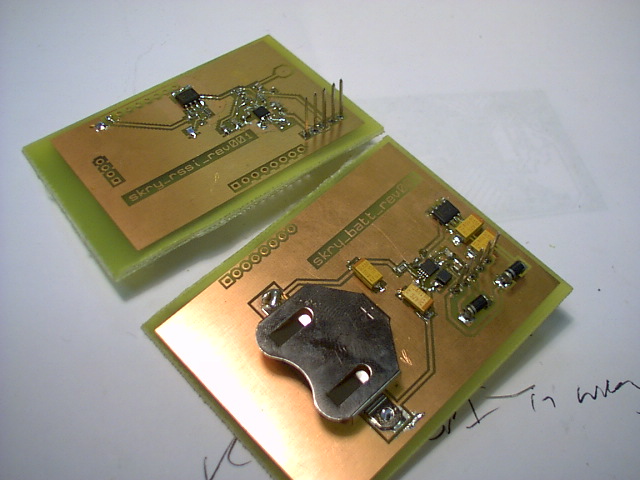
From top right [clockwise]: CPU sans memory for test only, AD8313 100Mhz-.2.4GHz broadband receiver, battery, wireless spectrum analysis, USB

A few (of my) mistakes.
[for conceptual detail please refer to http://scrying.org]
1] Main scrying board - AVR microcontroller and 512KB RAM:
[note: one jumper is missing on this board]
Board:

Schematic:
http://1010.co.uk/images/scrymain_newmemory.pdf
tar.gz of all KiCad files:
http://1010.co.uk/skrymain_rev001.tar.gz
superseded by:
http://1010.co.uk/skrymain_rev002.tar.gz
2] Battery board - with voltage regulation:
Board:

Schematic:
http://1010.co.uk/images/skrymain_rev001battery.pdf
tar.gz of all KiCad files:
http://1010.co.uk/images/skrybattery_rev001.tar.gz
3] USB connection board:
Board:

Schematic:
http://1010.co.uk/images/skry-usb-rev001.pdf
tar.gz of all KiCad files:
http://1010.co.uk/skryusb_rev001.tar.gz
http://1010.co.uk/skry-usb-rev001.brd
http://1010.co.uk/skrymain_rev001.brd
http://1010.co.uk/skrymain_rev001battery.brd
Schematics to follow shortly...
Unknown library with CR2450_KEYSTONE battery holder part for CR2450 battery. Exported from design at:
http://wiki.blinkenarea.org/bin/view/Blinkenarea/
1] In Eagle, Open Board then - File->Run->exp-project-lbr.ulp
2] Exports board as .lbr file and opens library editor
3] From here File->Run->exp-kicad-lib.ulp to convert to KiCad .mod
4] This last script is available from:
http://www.philcovington.com/BAK/exp-kicad-lib.ulp
file misaligned:
1] Plot settings - Gerber, plot origine: absolute, spot min: 0.015, Lines Width: 0.0010, all other settings though greyed out must be as defaults
2] Drill export settings - suppress leading zeroes, 2:4, drill origine: absolute, via drill 0.025, drill sheet: none
3] Check alignment using gerbv: http://gerbv.sourceforge.net/
free Gerber view package (KiCad's gerbview does not yet support examination of .drl drill files)
4] Check also by way of:
https://www.freedfm.com/!freedfmstep1.asp

1] Using BatchPCB [ http://www.batchpcb.com/faq.php ] for single prototype board. [ also looked at http://www.pcbcart.com/ but here we have DRC (Design Rules Checking) with email response.
2] Notes for using KiCad to set dimensions correctly (tracks and clearances as 0.01/10mil inches) and export correct Gerber files (in plot - check using gerbview) and drill files:
http://reprap.org/bin/view/Main/
3] We placed border using line/polygon tool on edge layer and then specified this in BatchPCB after upload (uploaded zip file with .drl drill file and all necessary .pho Gerber files.
[total $50 inc. postage for one prototype board approx 3 sq ins]
Towards construction of a test board integrating ATmega128, RSSI (AD8303), and 802.11 spectrum analysis, serial and USB connection):
(headers also from conrad)
all SMD (0805) where possible:
128:
RSSI:
Spectrum:
Serial/USB (now using RL chip):
Also parts for 3.3v to 5v voltage regulation:
References:
Serial: http://www.geocities.com/vsurducan/electro/PIC/pic84lcd.htm
USB: http://www.sparkfun.com/commerce/present.php?p=BEE-8-
Spectrum: http://www.wireless.org.au/~jhecker/specan/
3.3V: http://www.arduino.cc/en/uploads/Main/arduino_bt06.pdf
Question of Palm Pilot level conversion
is fine scrying_tech_notes but other way.
eg. using terminal on Palm Pilot as entry system for annotations
1] tried using (insert-file-contents "/dev/ttyS0") which works but only after Ctrl-G this command do the characters appear.
2] modified pilot.el and memo-pilot-el from emacs-pilot-1.4 to work with importing memos to file - change to import into annotations buffer and also to avoid repetition - test export of memos
3] Kermit script:
http://linuxdevices.com/articles/AT5085702347.html
(but is not directly into buffer)
4] C - read one character wrapped in: (insert (shell-command-to-string COMMAND))
TODO
http://1010.co.uk/images/scrymain_newmemory.pdf
For main board (rather messy) with:
1] Changes to programming interface
2] Breakout of SPI for radio
3] new 68512 512Kb SRAM
also http://1010.co.uk/images/628512.lib library for KiCad
[with atmegascheme more or less in place...]
1] If we expand to 512K say using the 628512 (Hitachi by way of Reichelt) then we need 19 bits for each memory address and thus increases size of list pointers in interpreter. [16 banks 32k (16 bits)]
2] Question of availability of either CC2420 and NRF905 radio chips. Also if we use SPI bus on ATmega128 for communication with either of these.
3] Redesign of main memory board for 512K addressing (latches), fixed programmer header and SPI throughput.
4] Brief look over solar charging possibilities and designs - 2.4v from batteries (2xAAA. say 700 mAh), Maxim MAX1758 and associated voltage reg. chips. See references.
Quick references:
Memory access: http://www.mikrocontroller.net/topic/15889
TinyOS CC2420 codebase
CC2420 board: http://www.rfsolutions.co.uk/acatalog/:_Zigbee_Module.html
NRF905 and SPI: http://www.avrfreaks.net/index.php?name=PNphpBB2&file=viewtopic&t=47356
50mA flexible solar panels: http://store.sundancesolar.com/3vol50maflex.html
[or they have 100mA 3.6v]
Harnessing Solar Power with Smart Power-Conversion Techniques:
http://www.maxim-ic.com/appnotes.cfm/appnote_number/484
From ActorNet paper: [http://osl.cs.uiuc.edu/docs/actornet/kwonActorNet.pdf]
The callcc operator accesses the current continuation (CC)—an abstraction of the rest of the program remain- ing to execute. For example, the CC of the expression (add 1 (mul 2 ↓ 3)) at the ↓ mark can be regarded as a single-parameter function c1: (lambda (x) (c2 (mul 2 x))), where c2 is an another single-parameter function (lambda (x) (add 1 x)). In general, the CC can be regarded as a stack of single-parameter functions. The operand of callcc is a single-parameter function: when callcc is called the CC is passed to the operand function.
In actorNet, the CC and the value that will be passed to it form the state of an actor. Because an actor can read its current continuation, it can duplicate itself or migrate to an- other platform voluntarily by sending its continuation–value pair to another actor. The other actor simply evaluates the continuation on the value to duplicate the sender’s behavior.
For our own work stressing remote execution and concurrency:
Each ActorNet platform hosts a launcher actor which regards messages sent to it as programs and evaluates them.
Actors rather than iterated execution. User as actor in environment also.
Other features:
[from above paper also]
Other Schemes of note:
Icbins: http://www.accesscom.com/~darius/hacks/icbins/
Minischeme: ftp://ftp.cs.indiana.edu/pub/scheme-repository/imp/minischeme.tar.gz
s9fes: http://t3x.org/bits/s9fes/
Tinyscheme: http://tinyscheme.sourceforge.net/home.html
1] We wrap avrdude in a shell script. Now changed for 128 or 128L to:
avrdude -p m128 -c avrusb500 -e -U flash:w:"$pfile"
[programmer from: http://tuxgraphics.org/electronics/200510/article05101.shtml ]
2] ATmega128 does not use MOSI and MISO pins but rather PDI and PDO (pins 2 and 3, shared with serial RXD0 and TXD0) - all respectively...
So programming breakout should go to: 1.RESET//2.PDI//3.PDO//4.SCK/5.GND
and then it works.

(1230 as used in ap0201) for scrying as size, cost and power consumption too high as compared to 62256 SRAM SMD chip.
well four as RSSI/signal strength is also included
When looking at chips listed below (to include also power consumption under TX, RX and any sleep conditions).
Installation: http://www.tinyos.net/tinyos-2.x/doc/html/install-tinyos.html
Tutorial: http://www.tinyos.net/tinyos-2.x/doc/html/tutorial/lesson1.html
Note source is in /opt/tinyos-2.x
... now ATmega128 (low power) board:
[this is the reduced test board sans SRAM]:
http://1010.co.uk/images/scrymain_reduced-Component.pdf
http://1010.co.uk/images/scrymain_reduced-Copper.pdf

To be tested (1/ test fuse bits for 8 MHz 2/ programming 3/ serial)
Further links for ATMega Scheme implementation:
XS: Lisp on Lego MindStorms: http://www.yuasa.kuis.kyoto-u.ac.jp/~yuasa/xs/index.html
Scheme implementation for AVR-based Mica-series wireless sensor nodes:
http://osl.cs.uiuc.edu/nest/:-1.1.tar.gz
In PCBNEW:
PgUp and PgDn or Shift V to switch component/copper side when laying tracks and vias (to place via start on component side, drag track, right click to place via and then track continues on copper side)
F1 zoom in
F2 zoom out
F3 redraw (across also all kicad apps)
F4 centre at cursor
and further see also: http://xtronics.com/reference/kicad.html
TODO: check SMD sizes and quartz surface mount footprint
http://1010.co.uk/images/scrymain.pdf
Notes:
1] All power/conditioning is done on power module board (but thinking about it maybe put some capacitors across Vcc/GND close by - maybe not- TODO) - thus we expose 5v/3.3v input - 8x ADC, 8x digital pins, serial stuff
Notes:
1] Plenty of very useful libraries inc. for ATmega128 and the Hitachi 32Kx8 Static RAM: 62256 (also from Reichelt) at:
The ATmega128 at: http://library.oshec.org/library/avr.lib
62256: http://library.oshec.org/library/memory-hitachi.lib
2] Making and connecting buses:
From Kicad online help:
In fact, due to the repetition command (Insert key), connections can be very quickly made in the following way, if component pins are aligned in increasing order (a common case in practice on components such as memories, microprocessors…):
Place the first label (for example PCA0)
Use the repetition command as much as needed to place members. EESchema will automatically create the next labels (PCA1, PCA2…) vertically aligned, theorycally on the position of the other pins.
Draw the wire under the first label. Then use the repetition command to place the other wires under the labels.
If needed, place the bus entries by the same way (Place the first entry, then use the repetition command).
Which boils down to:
ADC - 4 pins for I/O board: PC0/3
Serial TX/RX - 2 pins for USB: PD0/1
Digital - 8 pins for I/O board: PD0/7
Programming - PB3/5 + reset (below)
GND/Power - 2 pins
Crystal OSC (16 MHz) and 2 caps (18pF) to: PB6/7 [Xno breakout]
Reset (PC6) for programmer
//could also break out all of PD0/7 - but we do need 16 pins for address and data to NVRAM - this would use PD0/7 and PC0/3 and some of PB shared with I/O board/programming
...is a bit messy
and we also need 3 control lines for NVRAM: ALE/RD/WR (PB0/2)
so have to multiplex (there are 20 lines I/O - we need 19 for memory so in theory 1 line (same maybe as ALE high/low for RAM) can latch I/O board (just PC0/7 - shared analogue/digital I/O))
...or use the larger/more expensive ATmega128...
We could either use comint (seperate process) and small C code or use:
(defvar device "/dev/ttyS0")

(defun scry-hello (command)
  (shell-command (format "echo -n \"%s;\" > %s" command device)))
xbee module also:
http://www.maxstream.net/products/xbee/xbee-oem-rf-module-zigbee.php
and:
http://itp.nyu.edu/~raf275/meshnetworking/XBee/XBee_example.html
http://mrtof.danslchamp.org/AXIC - Arduino Xbee Interface Circuit
Note also 3v parts: Atmega8L is 3v version (or use 168 part and in case of Arduino Bluetooth (3.3v and 5v needed use of MAX1676 DC-DC convertor and MC33269D-3.3 regulator)
http://www.ethernut.de/en/hardware/enut1/index.html
ripe for meshing.
http://www.chipcon.com/index.cfm?kat_id=2&subkat_id=12&dok_id=115
see also:
http://www.tinyos.net/scoop/special/hardware#telosplatform
oh, and also:
http://www.atmel.com/products/AVR/z-link/Default.asp
Samsung k6x0808c1d SRAM 32 KB from segor.de:
interfaced using 74HC573 latch in design borrowed from:
http://www.ethernut.de/pdf/enut130g-s1.pdf
secret is to send alternating 1s and 0s as stream (170) with code (133) in the middle:
  beginSerial(BAUD);
  while(1){
    x++;
		      serialWrite(170);

		      if (x>=55) {
		       PORTC|= (1<<PC5);
		       serialWrite(133);
		       x=0;
		      }


Multichannel Intelligent Radio Transceiver Module
Laipac RLP/TLP4333 etc.
http://www.sklep.propox.com/index.php?d=produkt&id=1782
... using Makefiles for testsend.c and testreceive.c
... serial communications working with pin 3 as TX and pin 4 as RX and obviously both boards sharing common ground (test code flashes once every second local LED, sends serial code (133), and receiever code waits for this to flash)
... using LPRS 400T/R 121 ... poor results sans/with antenna and these need to be properly grounded
transmission and reception
antenna design (printed on PCB)
(untuned and tuned modules to test)
Manchester encoding
Possible chips - range (LOS), power consumption:
1] Cypress CYWUSB6935 2.4GHz DSSS radio transceiver (WirelessUSB-LR - 50m)
and 6936 samples from:
as used in the iDwaRF:
http://www.chip45.com/index.pl?page=iDwaRF-168&lang=en&tax=1&dest=0
RX: 57,7 TX @ 10 dBm - 69,1 !
2] LPRS:
http://www.lprs.co.uk/main/product.info.php?productid=259
The 400T/R 121:
FM transmitter & receiver for long range application up to 1km 433 MHz
3] Low power:
CC1000 from http://www.chipcon.com/index.cfm?kat_id=2&subkat_id=12&dok_id=14
see also:
http://www.tinyos.net/tinyos-1.x/doc/mica2radio/CC1000.html
and:
http://www.mikrocontroller.net/topic/42442
Chipcon CC2420 (2.4 GHz Zigbee-compliant with stack) - is used by open source Telos wireless sensor network design
(RX: 19.7 mA, TX: 17.4 mA)
4] http://www.abacom-tech.com/data_sheets/ATX-433-IAuser.pdf
5] From Nordic Semiconductors:
nRF905: 433/866... 200m line of sight
used in this module:
http://www.sparkfun.com/commerce/product_info.php?products_id=153#
(RX: 12.5. TX: 28 at 10dBm to 10 at -14)
nRF24L01: 2.4 GHz. 80m LOS.
11 mA (peak TX) at -0 dBm output power, dropping to 7 mA (peak TX) at -18 dBm output power. In receive mode (RX) the device requires 12.5 mA when receiving at its maximum rate of 2 Mbit/s.
for power see: http://www.msc-ge.com/frame/e/produkte/ele_kom/rf_dev/rf_components.html
6] XBee:
http://www.maxstream.net/products/xbee/dev-kit-zigbee.php
LOS:
XBee: 100m XBee-PRO: 1.6 km but outside European legislation
Transmit Current: XBee: 45 mA (@ 3.3 V) XBee PRO: 270 mA
Receive: 50 and 55 respectively
___
see also: