Covering programming the ATmega8 (as test case/example), ATmega128 (and any AVR 8-Bit RISC Microcontroller from Atmel) using free software tools on the GNU/Linux platform:
setup of target microcontroller:
ATmega8:
ATmega168:

ATmega128:

For our choices of programming hardware we make use of an ISP (in system programming) interface which accesses the programming hardware on the following pins (ATmega8):
Pin 22 : GND
Pin 19: SCK
Pin 18: MISO
Pin 17: MOSI
Pin 1: RESET
(and in this order from our three selected programmers)
And for the ATmega128 we use PDI/PDO rather than MISO/MOSI as follows:
Pin 22 : GND
Pin 11: SCK
Pin 3: PDO
Pin 2: PDI
Pin 20: RESET
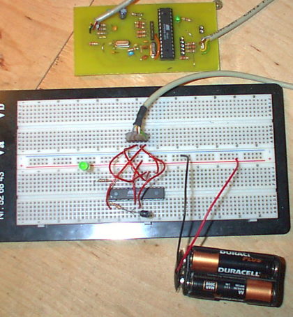
ATmega8 breadboard:

Notes for ATmega8: VCC (+5v) on Pins 7 and 20, GND on 8 and 22, 8, 16 or 12 MHz XTAL across pins 9 and 10 which also have two 22 pF capacitors to GND. Reset (pin 1) has one 10K resistor to +5v.
Using sensor board as target platform:
Using the new sensor board design close the top right jumper (pin_array_2) to allow for programming. Using the old design no changes necessary. Programming header (P1) makes use of pins outlined above in the correct order from right to left.
programmer construction:
Three programmers are covered here with pins/ISP as above:
1] AvrUsb500:
From Guido Socher: http://tuxgraphics.org/electronics/200510/article05101.shtml
2] BSD-Programmer:
http://www.bsdhome.com/avrdude/
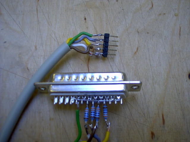
Connect 1K resistor between parallel port pins and all wires as follows EXCEPT the GND line of the parallel port (18-25):
Pins 18-25 (joined) : GND
Pin 8: SCK (1K)
Pin 10: MISO (1K)
Pin 9: MOSI (1K)
Pin 7: RESET (1K)
3] AVR-HID as usbasp programmer:

The usbasp/avr-hid in SMD format presents a standard 10 pin ISP (In System Programming) cable for programming all AVR parts. Pin outs as follows (with pin 1 as top right of the 10 pins):
1 MOSI
2 +5V
3 LED or n/c
4 GND
5 RESET
6 GND
7 SCK
8 GND
9 MISO
10 GND
There are also two vertical jumpers - the left is closed to program the device on the board ITSELF. The right is closed to program low frequency devices (important for standard 1 MHz).
Using code from: http://www.fischl.de/usbasp to program the ATmega8 on the AVR-HID board.
A new design (bringing out RESET and adding new jumpers) reflects minor changes needed to the (older) board design:

http://1010.co.uk/images/atmega8_minimal_usb-Copper2.pdf
The top left hand jumper (pin_array_2) is closed to set low frequency programming (needed for new parts using the internal oscillator). The top right hand jumper (also labelled pin_array_2) is closed to program the sensor board ITSELF.
programming software/process:
Many tutorials (see below) cover the use of avr-gcc to compile C code into hex code for easy upload to the target part. Here we cover using avrdude to upload the hex code to the chip using avrdude and the three programmers. Other programming/upload packages include uisp and ponyprog.
Avrdude:
http://www.bsdhome.com/avrdude/
sudo apt-get install avrdude

;; attach ISP header/cable (5 pins) to target.

;; apply POWER to target (from USB header or battery)

avrdude -c avrisp2 -p m8 -P /dev/ttyUSB0 -U flash:w:main.hex

;; to use the avrusb500 programmer (on usb serial port ttyUSB0) to
;; program main.hex on the ATmega8 part

avrdude -p m8 -c bsd -U flash:w:main.hex

;; for the BSD programmer (with port described in /etc/avrdude.conf)

avrdude -p m8 -c usbasp -U flash:w:main.hex

;; for our usbasp programmer
programming fusebits (and calculator):
Fusebits need to be programmed to make use of external oscillators, brownout detection and other functionalities outlined in the data sheet for the relevant part:
ATmega8: http://www.atmel.com/atmel/acrobat/doc2486.pdf
ATmega128: http://www.atmel.com/atmel/acrobat/doc2467.pdf
Fusebits can be programmed from the commandline or using avrdude interactively as follows (preferred):
;; first non-interactive

avrdude -c usbasp -p m8 -P /dev/ttyS0 -U lfuse:w:0xEC:m

;; to write to the low fuse

avrdude -p m8 -u -c usbasp -t -v -v

;; to invoke the interactive ardude session with the appropriate
;; programmer (and also in verbose mode)

w lf 0 0xff

w hf 0 0xdf

;; to write ff to the low fuse and df to the high fuse

;; and all in one!

avrdude -c avrusb500 -p m8 -P /dev/ttyUSB0 -U lfuse:w:0xFF:m -U hfuse:w:0xDF:m -U flash:w:main.hex
To figure out fuses refer also to the online AVR fuse calculator:
http://palmavr.sourceforge.net/cgi-bin/fc.cgi
A Makefile can also be used from within a code directory to simplify compilation (of multiple files), setting fuse bits and uploading code to the microcontroller.
useful references:
Programming the AVR microcontroller with GCC, libc 1.0.4:
http://tuxgraphics.org/electronics/200411/article352.shtml
Fuses: http://electrons.psychogenic.com/modules/arms/art/14/AVRFusesHOWTOGuide.php
avr-gcc: http://electrons.psychogenic.com/modules/arms/art/3/AVRGCCProgrammingGuide.php